AT32F435/437 Series Reference Manual
2022.11.11 Page 261 Rev 2.03
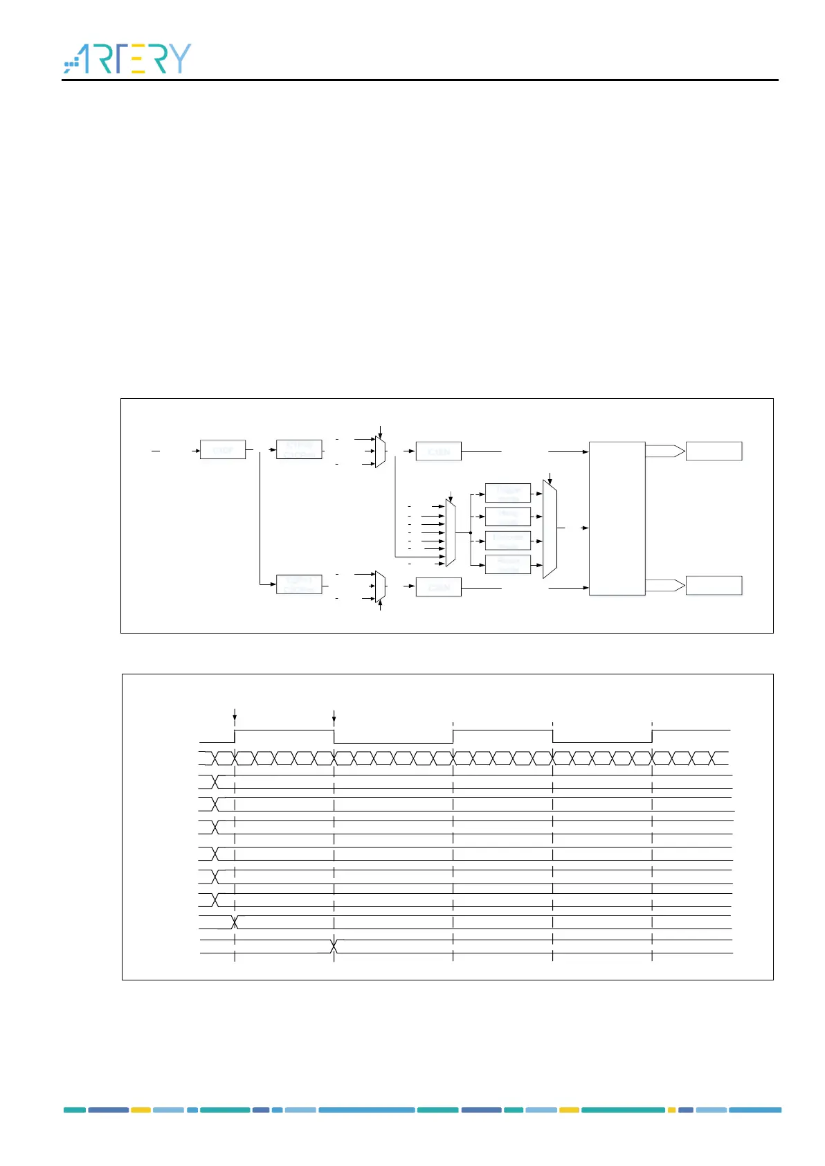
PWM input
The PWM input mode applies to channel 1 and channel 2. To enable this mode, map the C1IN and C2IN
to the same TMRx_CHx, and configure the CxIFPx of channel 1/2 to trigger slave timer controller reset.
The PWM input mode can be used to measure the period and duty cycle of input signal. The period and
duty cycle of channel 1 can be measured as follows:
Set C1C=2‘b01 to set C1IN as C1IFP1;
Set C1P=1’b0 to set C1IFP1 rising edge active;
Set C2C=2‘b10 to set C2IN as C1IFP2;
Set C2P=1’b1 to set C1IFP2 falling edge active;
Set STIS=3’b101 to set C1IFP1 as the slave timer trigger signal;
Set SMSEL=3‘b110 to set the slave timer in reset mode;
Set C1EN=1’b1 and C2EN=1’b1 to enable channel 1 and input capture.
In these configurations, the rising edge of channel 1 input signal triggers capture and saves captured
values to the C1DT register, and channel 1 input signal rising edge resets the counter. The falling edge
of channel 1 input signal triggers capture and saves captured values to the C2DT register. The period
and duty of channel 1 input signal can be calculated through C1DT and C2DT respectively.
Figure 14-184 Example of PWM input mode configuration
14.2.3.4 TMR output function
The TMR output consists of a comparator and an output controller. It is used to program the period, duty
cycle and polarity of the output signal.