ASCO Series 300 Quick Connect Power Panel
10 www.ascopower.com 381333-476
Set-up – Continued
6.
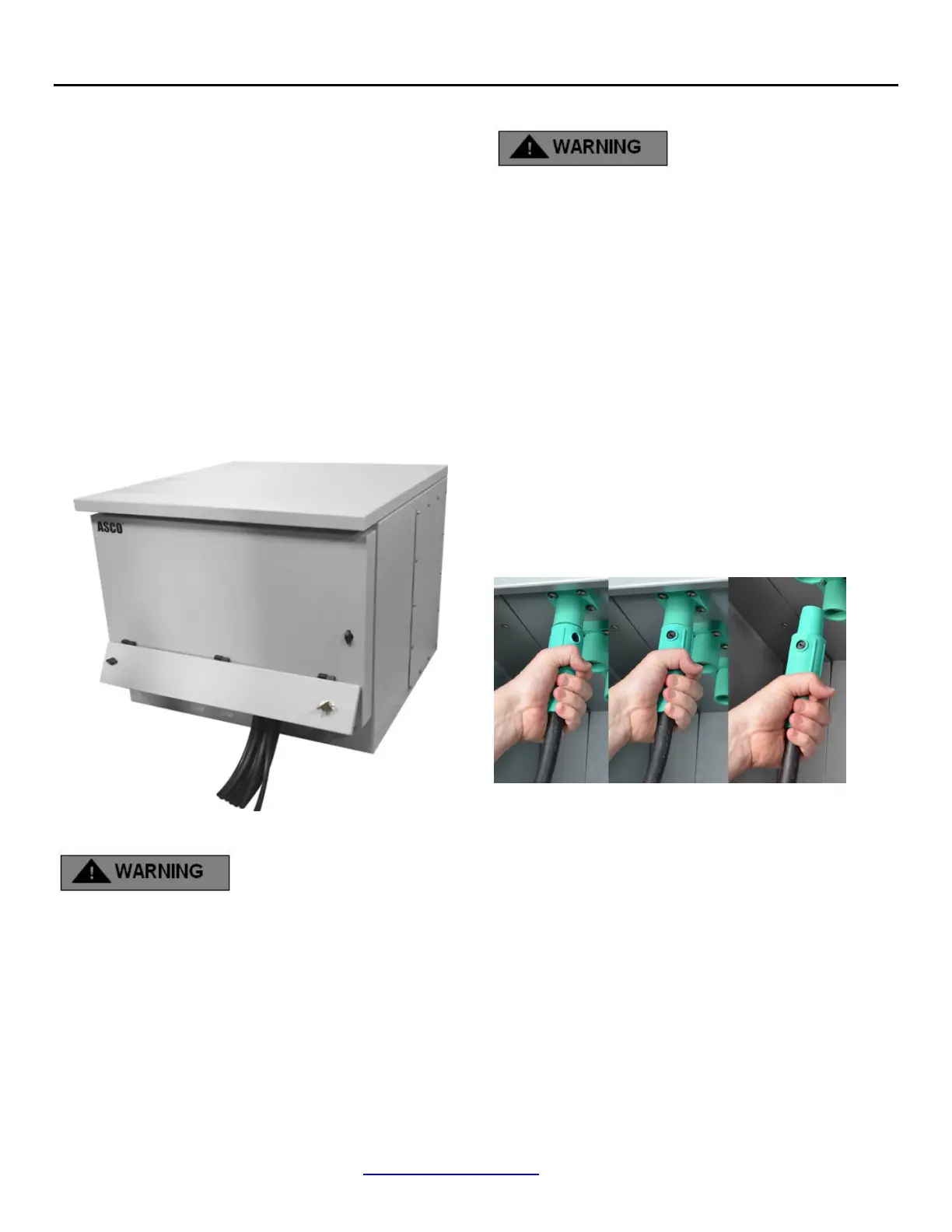
Complete the Phase (hot) connections
Proper connection (See Figure 8):
A.
Grasp connector jacket and firmly insert cam
connector
into cam plug
B.
Push on cam connector jacket until connector fully
seats
in cam plug
C.
Rotate cam connector jacket counterclockwise until
it
stops
Step 7: Close and lock lower chamber door,
allowing cables to exit through smaller
cable door (See Figure 11)
Figure 11
Step 8: Powering Up
Power MUST BE supplied from a source wired to a Transfer
Switch
1.
Toggle the transfer switch, diverting power from building
loads to load bank.
Step 9: Disconnection
DO NOT ATTEMPT DISCONNECTING
WHILE CIRCUITS ARE LIVE
Open lower chamber door
Order of disconnect
1.
Disconnect the Phase (hot) connections, beginning with
the
closest to the front door to the right.
Proper disconnection (See Figure 12):
1.
Grasp connector jacket firmly and rotate cam connector
clockwise until it stops
2.
Firmly pull on connector until it separates from the plug
3.
Set aside
2.
Continue with ALL Phase (hot) connections, beginning
with the front of the cabinet and working from front to
back
Figure 12
3.
Complete disconnect of ALL hot connections prior
to
proceeding
4.
Disconnect the Neutral (white) connection,
beginning
with the closest to the front door.
Proper disconnection (See Figure 12):
A.
Grasp connector jacket firmly and rotate cam
connector clockwise until it stops
B.
Firmly pull on connector until it separates from the plug
C.
Set aside

 Loading...