ASCO Series 300 Quick Connect Power Panel
6 www.ascopower.com 381333-476
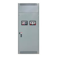
Step 5: Configuring the Phase Rotation
Monitor
A phase rotation monitor comes standard on all 2000A -4000A
pad mount Input panels. The Phase rotation monitor is
prewired from the factory for ABC rotation. (Figure 5)
1.
Should the phase rotation monitor configuration and
utility power (label found on the inside of
the door for the
Cam connection chamber) match, proceed to Step 6.
2.
Should the phase rotation monitor configuration and
utility power (label found on the inside of
the door for the
Cam connection chamber) differ, swap the A and B
phase rotation connection wires at the camlock
connection so it matches utility power and is consistent
with the label found inside the door.
Figure 5
Set-up
Step 6: Review Pre-Operation Checklist under
Appendix A prior to operation (pg. 8)
DO NOT ATTEMPT CONNECTION WHILE CIRCUITS
ARE LIVE
–
Do not use cables if they appear frayed
–
Do not use cable if connectors or plug do not seat properly
–
Do not use cables if any copper cabling is exposed
–
To limit risk of shock, disable generator automatic
start to
prevent unintended starting
Step 7: Determining phase rotation of generator
1.
Disconnect generator from all loads if needed
2.
Connect a phase rotation meter to the output phases
of the
generator
3.
Record generator phase rotation (clockwise or
counter-clockwise)
Step 8: Conduct a safety test to ensure proper
installation
1.
Do not attempt to use the ASCO Series 300 Quick Connect
Power Panel prior to
installation and completing the Pre-
Operation and Maintenance
Checklist under Appendix A
.
2.
Complete the Ground (green)connections, beginning
with the furthest from the from door to the left
Proper connection (Figure 6):
A.
Grasp connector jacket and firmly insert cam connector
into cam
plug
B.
Push on cam connector jacket until connector fully seats
in cam
plug
C.
Rotate cam connector jacket counterclockwise until it
stops
Step 9: Making Cam Connections
1.
Open main chamber door.
Figure 6
2.
Continue with connections, beginning with the rear of the
cabinet
and working forward
3.
Complete ALL Ground connections working from back to
front prior
to proceeding
4.
Complete the Neutral (white) connections, beginning with
the
furthest from the front door
Proper connection (Figure 6):
A.
Grasp connector jacket and firmly Insert cam connector
into cam
plug
B.
Push on cam connector jacket until connector fully seats
in cam
plug
C.
Rotate cam connector jacket counterclockwise until it
stops

 Loading...