ASCO Series 300 Quick Connect Power Panel
381333-476 www.ascopower.com
9
Installation – Output Panels
Continued from page 4
Step 3: Wiring the Bus Bars
Ensure circuit breakers are OFF and the transfer switch is
locked out from Source power prior to connection.
Failure to install transfer switch will create the potential for
the source to energize
the ASCO Series 300 Quick
Connect Output Power Panel and
endanger installation
personnel.
The ASCO Series 300 Quick Connect Output
Power Panel is for the connection of a Load
Bank to the Output terminals of a transfer switch.
1.
Pull the cables for the transfer switch to the ASCO
Series 300 Quick Connect Power
Panel
2.
Beginning with the ground, strip and install the cables in
the appropriate compression terminals
The terminals can accommodate #2 to 600MCM, Copper
wire only
3.
Tighten terminal screws to 375 lb-in torque each
4.
If metallic conduit is used, connect ground wire from
ground
bushing on conduit to the ground connection
point in the upper
right quadrant of the panel
5.
Ground conductor must be a minimum of #2 AWG
6.
Conduit shall NOT be relied upon to provide grounding
protection to tap box
7.
Vacuum entire upper chamber to ensure no metal
shavings are left
behind
Step 4: Conduct a safety test to ensure proper
installation
Do not attempt to use the ASCO Series 300 Quick
Connect Power Panel prior to
installation and
completing the Pre-Operation and Maintenance
Checklist under Appendix A
.
Set-up
Step 5: Review Pre-Operation Checklist under
Appendix A prior to operation (pg. 8)
DO NOT ATTEMPT CONNECTION WHILE CIRCUITS
ARE LIVE
–
Do not use cables if they appear frayed
–
Do not use cable if connectors or plug do not seat properly
–
Do not use cables if any copper cabling is exposed
–
To limit risk of shock, disable generator automatic
start to
prevent unintended starting
Step 6: Making Cam Connections
1.
Open lower chamber door
2.
Complete the Ground (green)connections, beginning
with the furthest from the from door to the left
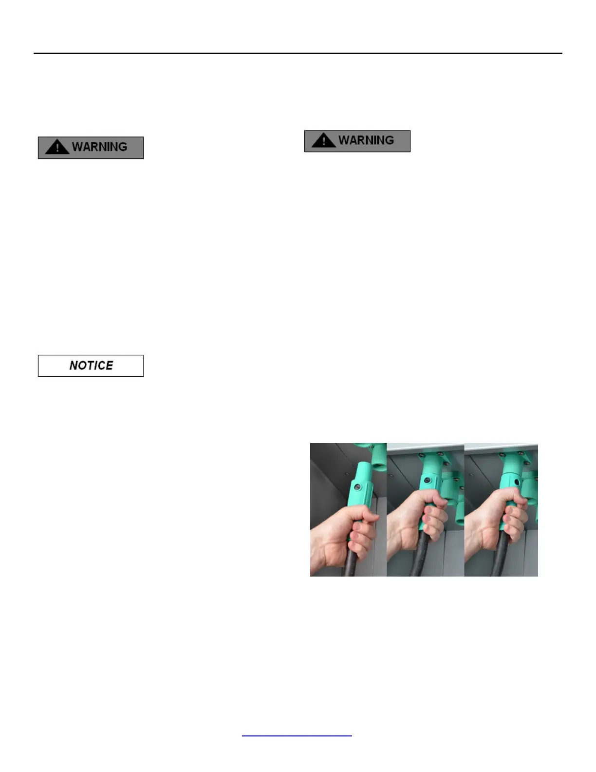
Proper connection (See Figure 10):
A.
Grasp connector jacket and firmly insert cam
connector
into cam plug
B.
Push on cam connector jacket until connector fully
seats
in cam plug
C.
Rotate cam connector jacket counterclockwise until
it
stops
Figure 10
3.
Continue with connections, beginning with the rear of
the cabinet and working forward
4.
Complete ALL Ground connections working from
back to front prior to proceeding
5.
Continue with connections, beginning with the rear of
the cabinet and working forward

 Loading...