ASCO Series 300 Quick Connect Power Panel
8 www.ascopower.com 381333-476
Step 12: Powering Up
Power MUST BE supplied from a single generator
1.
Start generator per manufacturer instructions
Toggle the transfer switch, diverting power from utility to
generator feed
Step 13: Disconnection
DO NOT ATTEMPT DISCONNECTING WHILE
CIRCUITS ARE LIVE
1.
To limit risk of shock, disable generator automatic start to
prevent
unintended starting
–
Open lower chamber door
–
Order of disconnect
2.
Disconnect the Phase (hot) connections, beginning with
the
closest to the front door to the right.
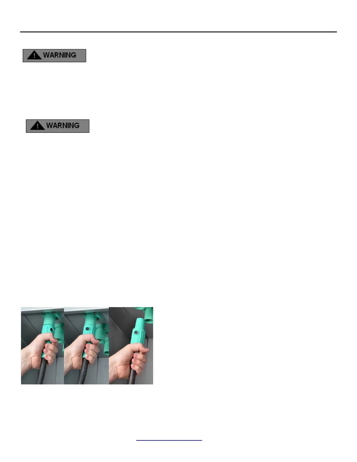
Proper disconnection (Figure 9):
A.
Grasp connector jacket firmly and rotate cam connector
clockwise until it stops
B.
Firmly pull on connector until it separates from the plug
C.
Set aside
3.
Continue with ALL Phase (hot) connections, beginning
with the front of the cabinet and working from front to
back
Figure 9
4.
Complete disconnect of ALL hot connections prior to
proceeding
5.
Disconnect the Neutral (white) connection, beginning with
the
closest to the front door.
Proper disconnection (See Figure 9):
A.
Grasp connector jacket firmly and rotate cam connector
clockwise until it stops
B.
Firmly pull on connector until it separates from the plug
C.
Set aside
6.
Continue with ALL Neutral (white) connections,
beginning with the
front of the cabinet and working from
front to back
7.
Complete disconnect of ALL Neutral connections prior to
proceeding
8.
Disconnect the Ground (green) connections, beginning
with the
closest to the front door
Proper disconnection (See Figure 9):
A.
Grasp connector jacket firmly and rotate cam connector
clockwise until it stops
B.
Firmly pull on connector until it separates from the plug
C.
Set aside
9.
Continue with ALL Ground (green) connections,
beginning with the
front of the cabinet and working
rearward
10.
Complete disconnect of ALL Neutral connections prior to
proceeding
Step 14: Secure front door to complete.

 Loading...