Nameplate and Catalog Numbe r Identification
The Transfer Switch nameplate includes data for each specific ASCO Series 300 ATS. Use the ATS only within the
limits shown on this nameplate. A typical Catalog Number is shown below with its elements explained.
The example is for a Series 300 ATS with switched neutral, 3 pole, 400 amp., 480 V, in a Type 1 enclosure:
E 300 C 3 400 N 1 C
Phase Poles
Neutral
Amperes Voltage Controller Enclosure
C – overlapping
1 –standard
G –type4
C –type1
F –type3R
L –type12
3 –threeØ
2 –singleØ
D 220
C 208
E 230
K 415
M 460
J 400
L 440
N 480
F 240
H 380
Q 575
P 550
R 600
400
260
blank – solid
blank – open type
1X –if
accessories
ordered
transfer switch
prefix letter
B 120
A 115
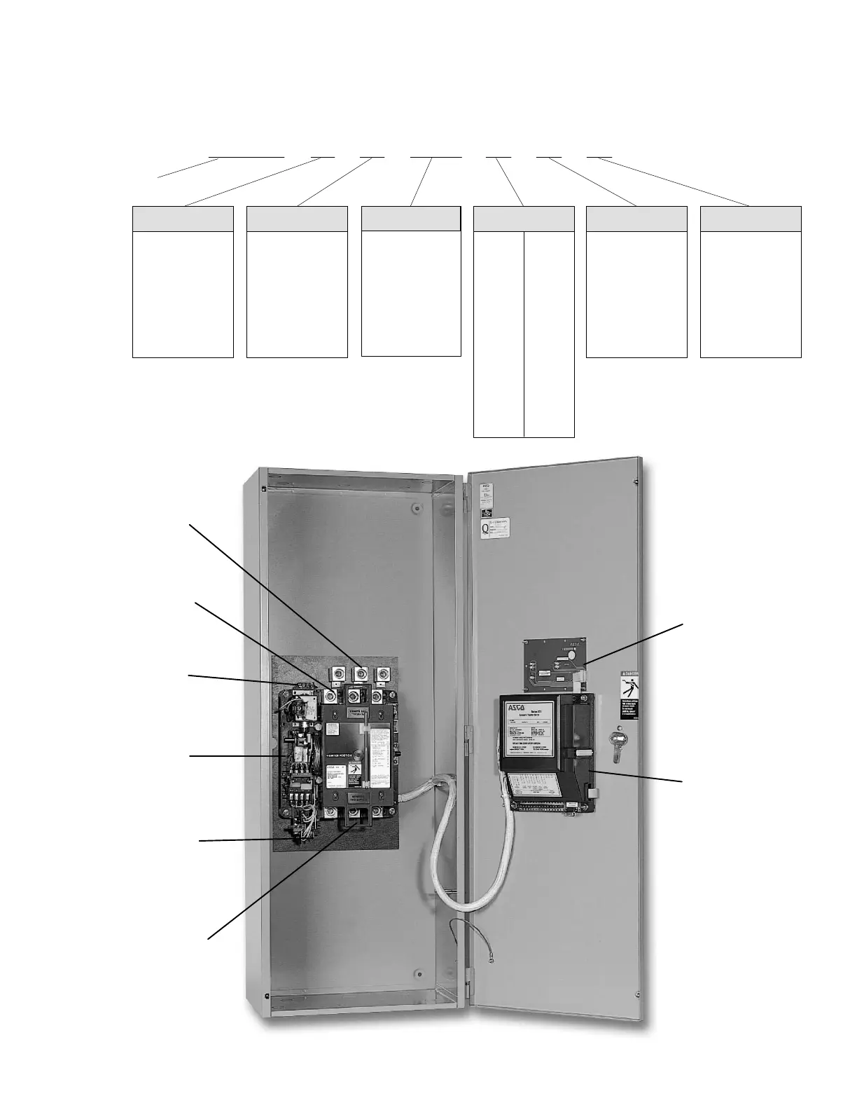
terminals for
engine start
contacts
Transfer
Switch
Controller
normal power
connections
emergency power
connections
membrane
controls
400 amp. size in typical enclosure with location of customer connections
terminals for
switch position
contacts
load power
connections

 Loading...