TD 92232GB
2005-06-15 / Ver.G
Installation Guide
ELISE2
12
System Installation
When the ELISE2 controls the communication on the A-bus, a maximum of 15 modules
can be connected to the A-bus. The ELISE2 should have the address 00 and other modules
that are connected to the A-bus must have addresses in the range 01-0F.
See also 4.16 Message Distribution on page 24 and documentation for the System 900.
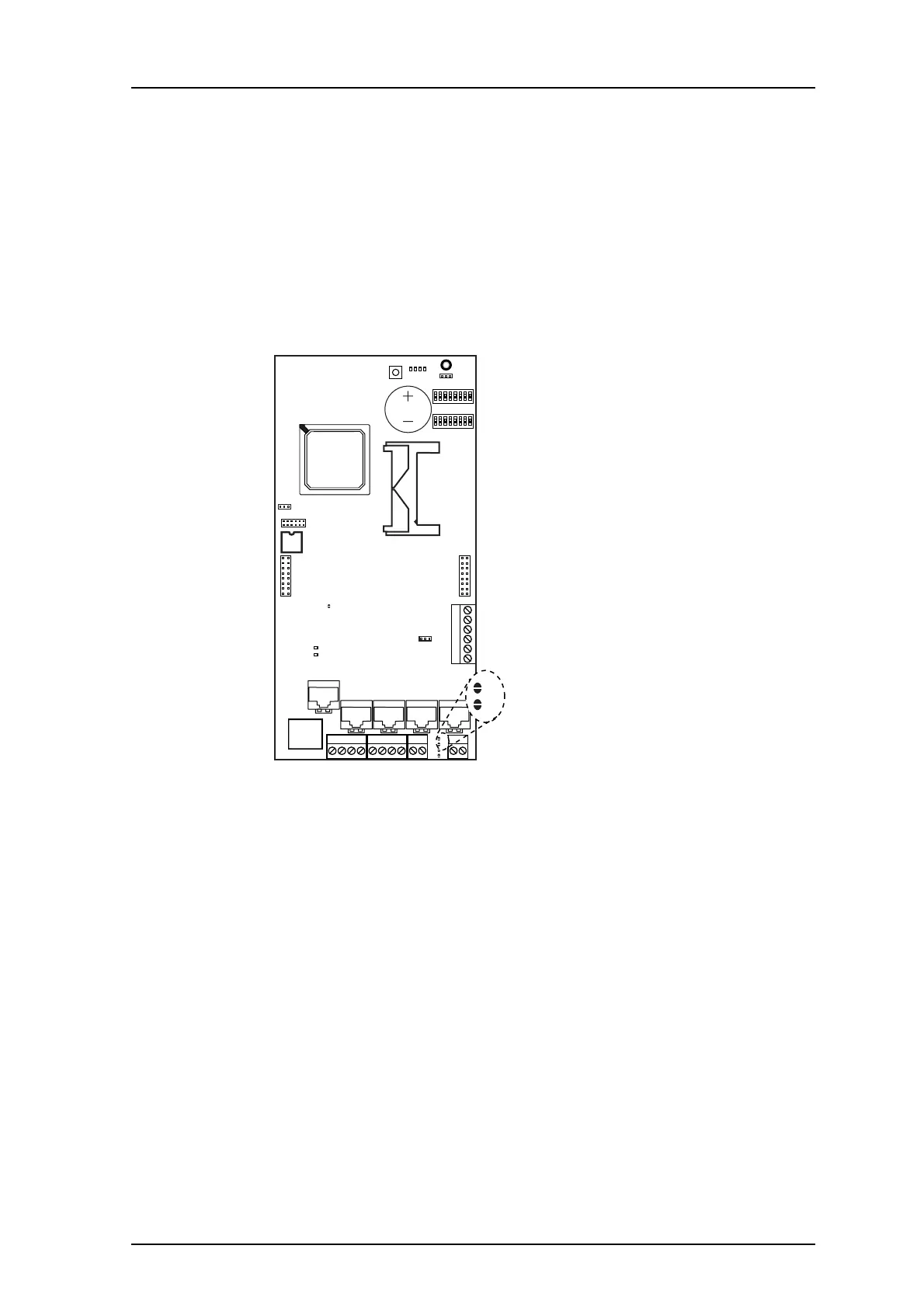
Required Hardware Modifications
When ELISE2 shall control the communication on the A/B-bus, jumper points S4 and S5
has to be soldered, see
figure 7 below.
Figure 7. Jumper points for configuring the ELISE2 unit to be a communication
controller on A/B-bus.
012
J7
J20
LED6
RS232:3
ETH
LED7
J2
J10
J16
J15
J4
J13J12J11J8
J24
J14J6J5
S3
900 900RS232:2 RS232:1
S4
S5
S1
S2
IC24
J22
J9
IC1
BAT1
SW4
LED1
J1
SW2
SW3
1
LED2
LED3
LED4
LED5
1
8
1
8
16
2
21
1414 1
S4
S5
S4
S5