TD 92232GB
2005-06-15 / Ver.G
Installation Guide
ELISE2
18
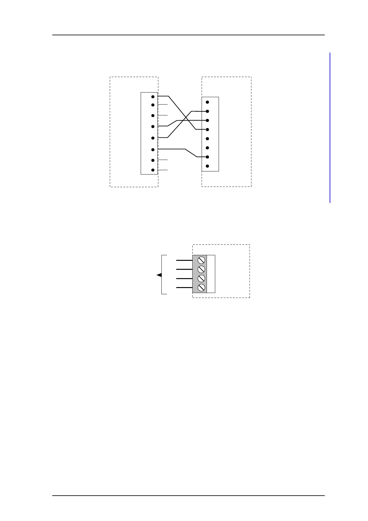
Connections for Serial Line Printer
To connect the serial line printer, see figure 14 for the pin-layout and wiring run.
Figure 14. Connections for serial line printing.
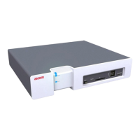
RS422 Communication with External Unit
Depending on software application the RS422 port is used or not. If it is used, the
connector J6 is connected to the external unit as shown in the figure below.
Figure 15. Connection of external unit via the RS422 port.
Connection of AUX Inputs and AUX Outputs
The application of the inputs and outputs are software dependent.
Two digital inputs and two digital outputs can be connected via J16. The outputs are of
open-collector type and the output signals are dimensioned for 100 mA at max 12 V.
A pull-up resistor should be connected to the output as shown in figure 16.
Galvanic isolation of the inputs and outputs is provided by using a separate power supply.
When galvanic isolation is not needed, supply voltage can be taken from the ELISE2 circuit
board by connecting J16-1 to J5-3 and J16-6 to J5-4.
1 (not used)
2 TX
3 RX
4 CTRL IN
5 CTRL OUT
6 (not used)
J11/J7/J8
7 GND
8 (not used)
ELISE
035
25-pin male
D-sub connector
DTR
DSR
DCD
TXD
RXD
GND
RTS
CTS
20
6
8
2
3
7
4
5
1 T(b)
2 T(a)
3 R(b)
4 R(a)
Rb
Ra
Tb
Ta
J6
To external unit
using RS422
communication
023