TD 92989EN
15 October 2014 / Ver. B
Installation Guide
IP-DECT Base Station & IP-DECT Gateway
16
DIP Switches
The DIP switches can be found on the back of the DB1, see figure 6 on page 14.
Note: DIP switch 3 and 4 shall be set to ON.
Set DIP switch 1 and 2 to ON or OFF as follows:
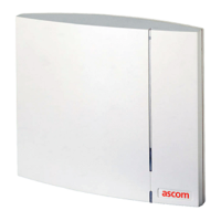
2.5.2 DB1 with External Antennas
This section contains the differences between the DB1 with internal antenna and the DB1
with external antennas. For all other information see 2.5.1 DB1 with Internal Antenna on
page 14.
Figure 7. DB1 with MCX connectors for external antennas.
Contents of the Box
The box in which the DB1 is packed contains:
• A DB1 with external antennas.
• A mounting bracket
• An antenna bracket
• Two antenna coaxial cables.
• Two antennas.
Error 100 ms red, 100 ms off. U
PN
layer 1 communication
error.
Fatal error Solid red. Fatal hardware error.
DIP switch 1: ON
DIP switch 2: ON
DB1 Standard (Europe, Africa, Middle East, Australia, New Zealand
and Asia) for use with DECT in the 1880-1900 MHz frequencies.
DIP switch 1: ON
DIP switch 2: OFF
DB1 SA (South America) for use with DECT in the 1910-1930 MHz
frequencies.
DIP switch 1: OFF
DIP switch 2: OFF
DB1 NA (North America) for use with DECT in the 1920-1930 MHz
frequencies.