EasyManuals Logo

ASCOM IP-DECT IPBS2 User Manual

ASCOM IP-DECT IPBS2
39 pages
To Next Page IconTo Next Page
To Previous Page IconTo Previous Page
Page #32 background imageLoading...
Page #32 background image
TD 92989EN
15 October 2014 / Ver. B
Installation Guide
IP-DECT Base Station & IP-DECT Gateway
29
4.2 Pin the IPBL Cable
All data cables used for the IPBL is standard CAT5 unshielded cable. It is assumed that
installation personnel know how to crimp these connectors to a cable.
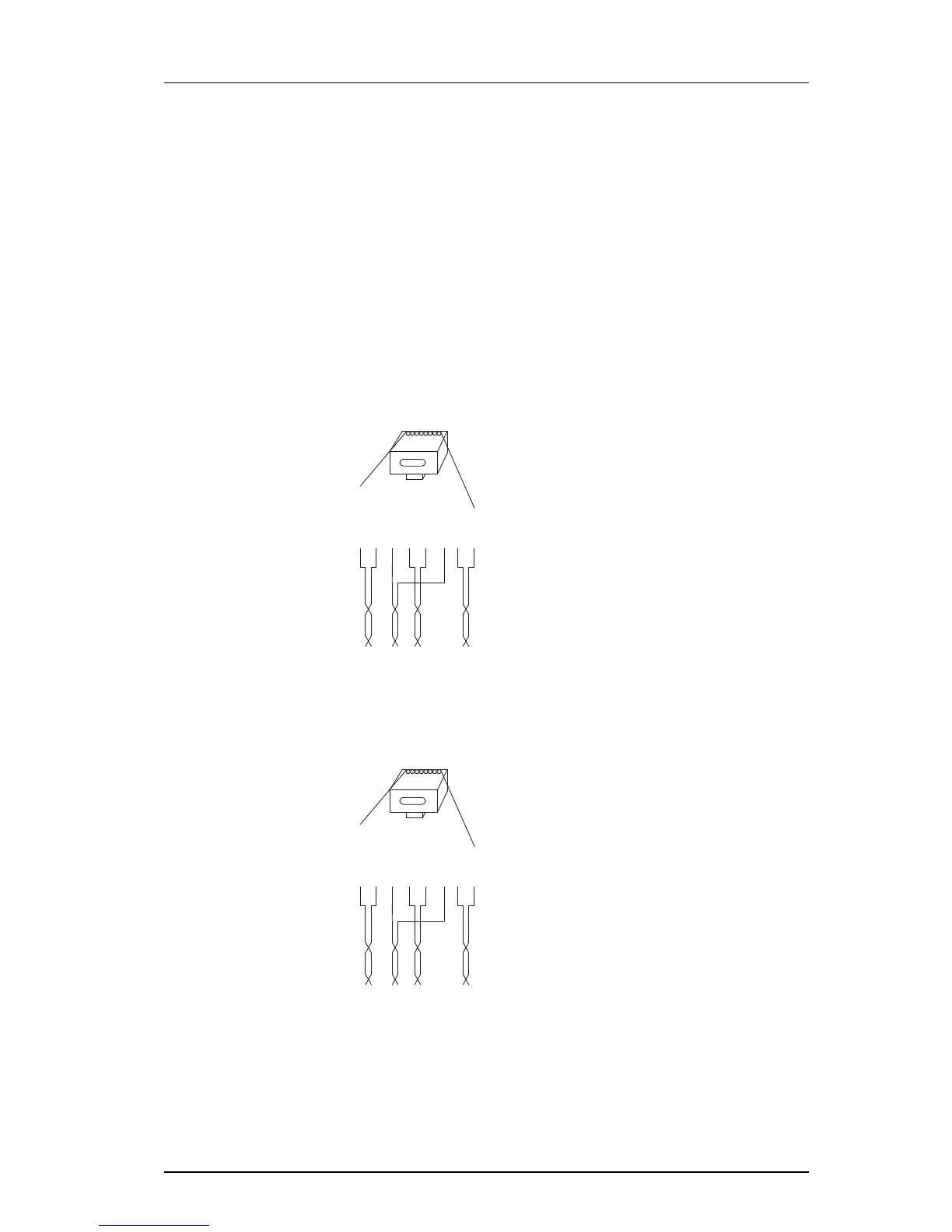
4.2.1 Synchronization Cable
The maximum cable length between two IPBLs mu
st not exceed 2000 meters.
1 Cut the cable to the correct length.
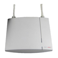
2 Connect the cable to a RJ45 modular jack. For information on pinning, see Figure
17 and Figure 18.
3 Label the cable.
Sync IN
RJ45
modular jack
Sign Tx +
Sign Tx -
Sign Rx +
Rx +
Rx -
Sign Rx -
Tx +
Tx -
Sign = Signalling
Rx = Reciever data pair
Tx = Transmitter data pair
026
15432678
Figure 17. Connector pinning of the Sync IN cable
Sync OUT
RJ45
modular jack
Sign Rx +
Sign Rx -
Sign Tx +
Tx +
Tx -
Sign Tx -
Rx +
Rx -
Sign = Signalling
Rx = Reciever data pair
Tx = Transmitter data pair
027
15432678
Figure 18. Connector pinning of the Sync OUT cable

Questions and Answers:

Question and Answer IconNeed help?

Do you have a question about the ASCOM IP-DECT IPBS2 and is the answer not in the manual?

ASCOM IP-DECT IPBS2 Specifications

General IconGeneral
BrandASCOM
ModelIP-DECT IPBS2
CategoryAccessories
LanguageEnglish

Related product manuals