Ascon Tecnologic - e31- - OPERATING INSTRUCTIONS - PAG. 5
4.3 Electrical connections
Carry out the electrical wiring by connecting only one wire to
each terminal, according to the following diagram, checking
that the power supply is the same as that indicated on the
instrument and that the load current absorption is no higher
than the maximum electricity current permitted.
As the instrument is built-in equipment with permanent con-
nection inside housing, it is not equipped with either switches
or internal devices to protect against current overloads: the
installation will include an overload protection and a two-
phase circuit-breaker, placed as near as possible to the in-
strument and located in a position that can easily be reached
by the user and marked as instrument disconnecting device
which interrupts the power supply to the equipment
It is also recommended that the supply of all the electrical cir-
cuits connected to the instrument must be protect properly, us-
ing devices (ex. fuses) proportionate to the circulating currents.
It is strongly recommended that cables with proper insulation,
according to the working voltages and temperatures, be used.
Furthermore, the input cable of the probe has to be kept sepa-
rate from line voltage wiring. If the input cable of the probe is
screened, it has to be connected to the ground at only one side.
Whether the instrument is a 12 V version (Power supply code
F) it is recommended to use an external TCTR transformer, or
with equivalent features (class II insulation) and to use only one
transformer for each instrument because there is no insulation
between supply and input
We recommend that a check should be made that the
parameters are those desired and that the application
functions correctly before connecting the outputs to
the actuators so as to avoid malfunctioning that may
cause irregularities in the plant that could cause dam-
age to people, things or animals.
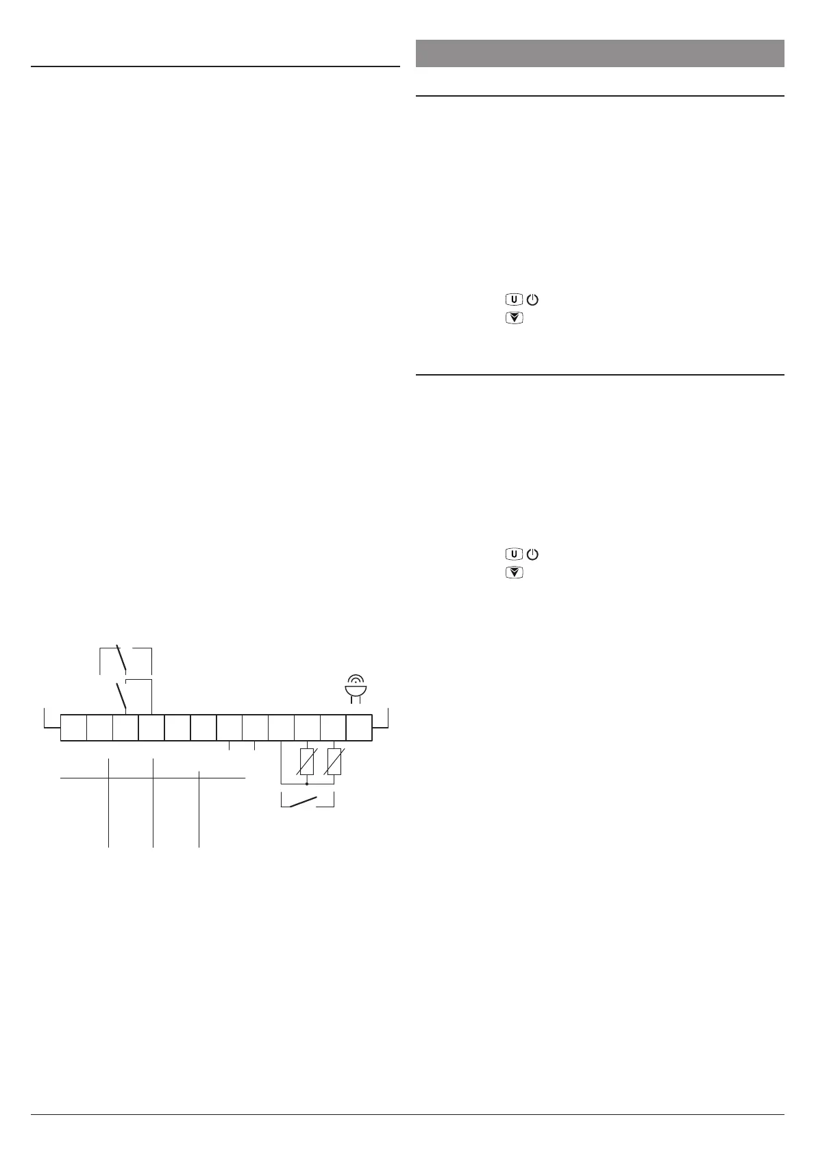
4.3.1 Electrical wiring diagram
(12 A max. for models with removable terminals)
16 FLA
96 LRA
15 A Res.
EN
30 (15) A
61810
Out (H):
15 (15) A
5 FLA
30 LRA
12 A Res.16 (9) AOut (R, S): 10 (4) A
60730
EN UL
Supply
1 32 4 65 7 98 10 1211
INPUTS
OUT
Pr1
Digital
Input
Pr2
Internal
Buzzer
SPST-NO
NONOC
SPDT
NONONC C
5. FUNCTIONS
5.1 ON/Stand-by function
Once powered the instrument can assume 2 different condi-
tions:
ON: Means that the controller uses the control functions.
STAND-BY:
Means that the controller uses no control function and
the display is turned off except for the Stand-by LED.
The transition between Standby and ON is equivalent to
power ON the instrument providing the electrical power
In case of power failure, the system always sets itself in the
condition it was in before the black-out
The ON/Stand-by function can be selected:
– With the key
/ pressed for 1 s if tUF = 3;
– With the key /Aux pressed for 1 s if tfb = 3;
– Using the Digital Input if parameter iFi = 7;
5.2 Normal and economic operation
This tool allows to pre-set two different Setpoints, one Nor-
mal - SP and one Economic - SPE.
Associated with each Setpoint there is the relative differential
(hysteresis): Normal - rd and Economic - rEd.
Switching between the two modes can be automatic or manual.
5.2.1 Normal/Economic operation selection
This function can be used when you need to switch two func-
tional temperatures (eg. Day/Night or week-day/week-end). The
Normal/Economic operation can be selected in manual mode:
– With the key
/ pressed for 1 s if tUF = 2;
– With the key /Aux pressed for 1 s if tFb = 2;
– Using the Digital Input if parameter iFi = 6.
The Normal/Economic operation can be selected in auto-
matic mode:
– Elapsed the iEt time after the door has been closed
(Normal/Eco switching).
– At door opening if the SPE Setpoint is activated by iEt
parameter (Eco/Normal switching).
– Elapsed the itt time after the door has been closed and
from the activation of SPE Setpoint by iEt parameter
(Eco/Normal switching).
To use this function, it is necessary to set the Digital Input as:
iFi = 1, 2 or 3.
If iEt = oF the selection of Eco/Normal modes via the digital
input is disabled.
If itt = oF the time-out switching from Eco to Normal mode
is disabled.
Switching to Economic mode is indicated by the label Eco.
When idS = Ec the Economic mode is pointed out with a
fixed Eco label otherwise the label Eco appears every 10 s
alternated to the display set with parameter idS.
The normal Set Point SP can be set to a value between the
one set with parameter SLS and the one set with parameter
SHS while the Economic Set Point SPE can be set to a value
between the one set with parameter SP and the one set with
parameter SHS.
 Loading...


