Ascon Tecnologic - e31- - OPERATING INSTRUCTIONS - PAG. 8
5.8 Alarm functions
The alarm conditions of the instrument are:
– Probe errors E1, -E1 and E2, -E2;
– Temperature alarms Hi and Lo;
– External alarm AL;
– Door open oP.
All active alarms are pointed out on the instrument display
lighting up the LED and, if configured with parameter obu,
also with the internal buzzer
Any active alarm condition is signaled lighting up the LED ,
while the acknowledged alarm status is shown by flashing the
LED .
The buzzer (if present) can be configured to point out the alarms
by programming parameter obu = 1 or 3 and always acts to
signal the acknowlegeable alarms. This means that, when
activated, it can be switched OFF by briefly pressing any key.
5.8.1 Temperature alarms
The temperature alarm works according to Pr1 or AU probes
measurement, the type of alarm set in the parameter AAy the
alarm thresholds set in parameters AHA (maximum alarm)
and ALA (minimum alarm) and the relative differential AAd.
Through parameter AAy it is possible to set the alarm thresh-
olds AHA and ALA as absolute or relative to the active Set
Point, must be related to Pr1 or Au probes and if the message
Hi (High alarm) and Lo (Low Alarm) are to be displayed at
alarm intervention.
Depending on the desired alarm operating mode, parameter
AAy
can be set as:
1 Absolute alarms referred to probe Pr1, displays Hi/Lo;
2 Relative Alarms referred to probe Pr1, displays Hi/Lo;
3 Absolute alarms referred to probe Au, displays Hi/Lo;
4 Relative Alarms referred to probe Au, displays Hi/Lo;
5
Absolute alarm referred to probe Pr1, displays no labels;
6
Relative alarm referred to probe Pr1, displays no labels;
7
Absolute alarm referred to probe Au, displays no labels;
8
Relative alarm referred to probe Au, displays no labels
.
Using some parameters it is also possible to delay the ena-
bling and the intervention of these alarms.
These parameters are:
APA
Temperature alarm exclusion time on switching ON the
instrument if the instrument is in alarm status when it
is switched ON. If the instrument is not in alarm status
when it is switched on the time APA it is not considered.
AdA Temperature alarm exclusion time at the end of de-
frost cycle (and, if programmed, after the draining) or
after a continuous cycle.
AAt Temperature alarms delay activation time. Tempera-
ture alarms are enabled at the end of the exclusion
times and are activated after the AAt time when the
temperature measured by the probe exceeds or goes
below the respective maximum and minimum alarm
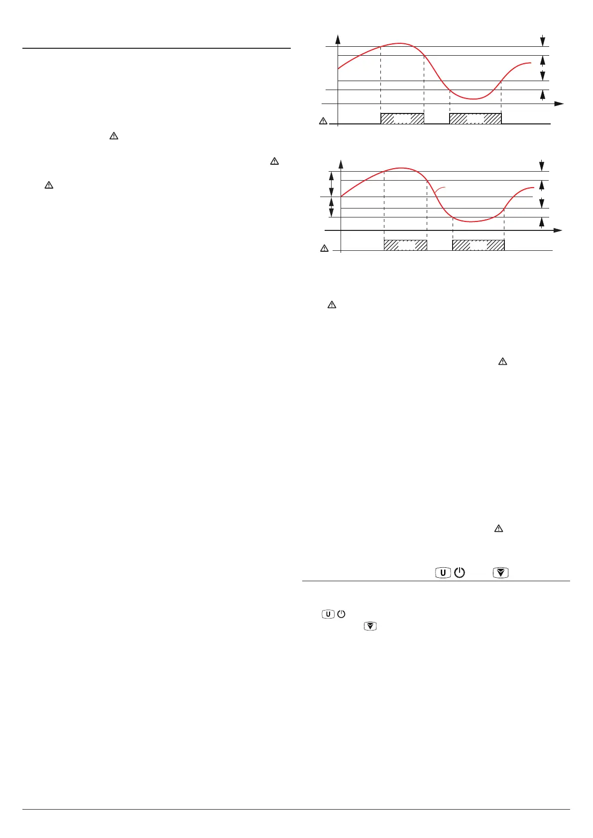
thresholds. The alarm thresholds are those set at
parameters AHA and ALA when the alarms are set as
absolute (AAy = 1, 3, 5, 7).
Temp.
AHA
AAd
time
AL
ALA
AAd
offoffoff
ON ON
Hi Lo
Pr1
or they assume the values [SP + AHA] and [SP + ALA]
if the alarms are relative (AAy = 2, 3, 6, 8).
AHA
SP
ALA
offoffoff
ON ON
Hi Lo
time
AL
AAd
AAd
Temp.
Pr1
The maximum and minimum temperature alarms can be disa-
bled by setting the related parameters AHA and ALA = oF.
The temperature alarms are signalled lighting up the alarm
LED ( ) and, if configured, also with the buzzer
5.8.2 External alarm from digital input
The instrument can signal an alarm external to the instrument
using the digital input setting iFi = 4 or 5. The instrument
signals the alarm turning ON the
alarm LED ( )
and display-
ing AL label alternated to the variable set with parameter Ids.
Mode iFi = 4 operates no action on the control output, while
iFi = 5 deactivates the control output at digital input inter-
vention.
5.8.3 Open door alarm
The instrument can signal the open door alarm condition using
the digital input setting iFi = 1, 2 and 3. As the Digital input is
activated, the instrument signals that the door is open showing
on the display the oP label alternated to the variable set with
parameter ids.
After the delay set with parameter AoA the instrument
signals the Open Door alarm with the configured devices
(buzzer and/or Output), lighting up the LED while showing
the oP label. At the open door alarm intervention are also
re-activated the inhibited outputs (compressor).
5.9 Function of keys / and /Aux
Two of the instrument keys, in addition to their normal func-
tions, can be configured to operate other commands.
The / key function can be defined using the tUF param-
eter while the /Aux key via parameter TFb. Both param-
eters have the same possibilities and can be configured to
perform the following functions:
oF The key carries out no function;
1. Do not use;
2. Pressing the key for at least 1 s, you can sequentially
select a normal or eco operating mode (SP/SPE).
A selection has been made the display shows for about
1 s the active set point code (SP or SPE);
3. Pressing the key for at least 1 s is possible to switch the
instrument from ON to Stand-by state and vice-versa;
4. Do not use.
 Loading...


