Ascon Tecnologic - e31- - OPERATING INSTRUCTIONS - PAG. 7
ment so that that the output continues to work in cycles
according to the times programmed with parameter rt1
(activation time) and rt2 (deactivation time).
If an error occurs on the probe the instrument activates the
output for the time rt1, then deactivates it for the time rt2
and so on whilst the error remains.
Programming rt1 = oF the output in probe error condition
remains switched off.
Programming instead rt1 to any value and rt2 = oF the
output in probe error condition remains switched ON.
Remember that the temperature regulation function can be
conditioned by the Compressor Protections, Delay at power
ON and Defrost functions.
5.6 Compressor protection function and
power-on delay
The “Compressor Protection” function aims to avoid repeated
compressor start-ups controlled by the instrument in cooling
applications or otherwise can be used to add a timed control
on the actuator control output.
This function foresees 3 time controls on the switching ON of
the output associated with the temperature control request.
The protection consists of preventing the output being
switched ON during the times set with parameters PP1, pP2
and PP3 and therefore that any activation occurs only after
all times are elapsed.
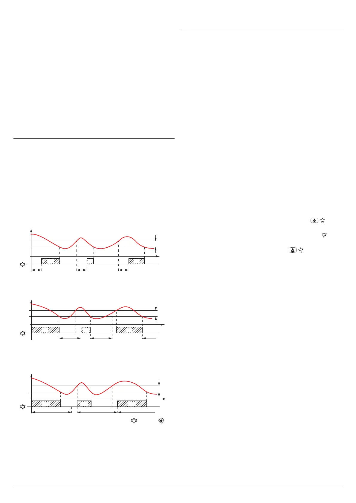
1. First control (parameter PP1) foresees a delay to output
activation (switching-ON delay).
SP
time
offoff off off
ON
rd
PP1 PP1
PP1
PP1
OUT (ot)
Pr1
ON ON
2. Second control (parameter PP2) foresees an inhibition to
the activation of the output by a time delay that starts when
the output is turning OFF (delay after switching-OFF).
SP
offoff off
ON
rd
PP2 PP2 PP2
PP2
Pr1
time
OUT (ot)
ON ON
3. Third control (parameter PP3) foresees an inhibition to
the activation of the output by a time delay that starts
when the output was turned ON last time (delay between
two switching-ON).
SP
offoff off
ON
rd
PP3 PP3PP3
time
OUT (ot)
PP3
Pr1
ON ON
During the output inhibition the LED OUT (Cool or Heat )
blinks. It is also possible to prevent activation of the output
after the instrument is turned ON, for the time set in the
parameter Pod.
During the power ON delay phase, the display shows the
indication od, alternated with the normal visualization.
All these functions are disabled if the relative parameters are
set to OFF (oF).
5.7 Defrost control
The automatic defrost control is made with the stopping
compressor method; it occurs by interval times or after a
certain time of continuous compressor functionning.
The automatic defrost function is activated when at parameter
ddi is set the defrost interval time between 2 defrost cycles.
The first defrost after power on can be set by parameter dSd.
This allows to perform the first defrost to a different interval
from
ddi
time.
When the instrument must perform a defrost cycle at all power
ON, set parameter dSd = oF.
If all defrost cycles must be performed after the same inter-
val time, program dSd = ddi.
Automatic defrost function is totally disabled when ddi = oF
(including the first, regardless the time set at dSd parameter).
The instrument provides to switch OFF the output for the
ddE period of time every time expires the ddi time (or dSd
in case of first defrost after power ON).
Moreover, the instrument starts a defrost cycle when the
compressor is activated continuously for the time dcd.
This function is used as the continuous operation of the com-
pressor for a long period is normally a symptom of a low heat
exchange typically caused by the frost on the evaporator.
By setting dcd = oF the function is disabled.
5.7.1 Manual defrost
To start a manual defrosting cycle, press the key / when
it is not in programming mode and keep it pressed for about
5 s after which, if the conditions are correct, the LED will
light up and the instrument performs out a defrosting cycle.
To stop a defrosting cycle, press the key / during the
defrost and keep it pressed for about 5 seconds.
5.7.2 Display lock during Defrost
Through parameters ddL and AdA it is possible to define the
display behaviour during defrost. The ddl parameter can as-
sume the following values.
on The ddL parameter locks the display at the last tem-
perature reading during all the defrost cycle until, at
the end of defrost, the temperature has not reached
the lock value or the value [SP + rd] or is elapsed the
time set at parameter AdA
Lb Shows the label dEF during the defrost cycle and PdF
after the defrost until, at the end of defrost, the tem-
perature has not reached the lock value or the value
[SP + rd] or is elapsed the time set on parameter AdA
oF The display continues showing the temperature meas-
ured by the Pr1 probe during the defrost cycle.
 Loading...


