Ascon Tecnologic - e31- - OPERATING INSTRUCTIONS - PAG. 6
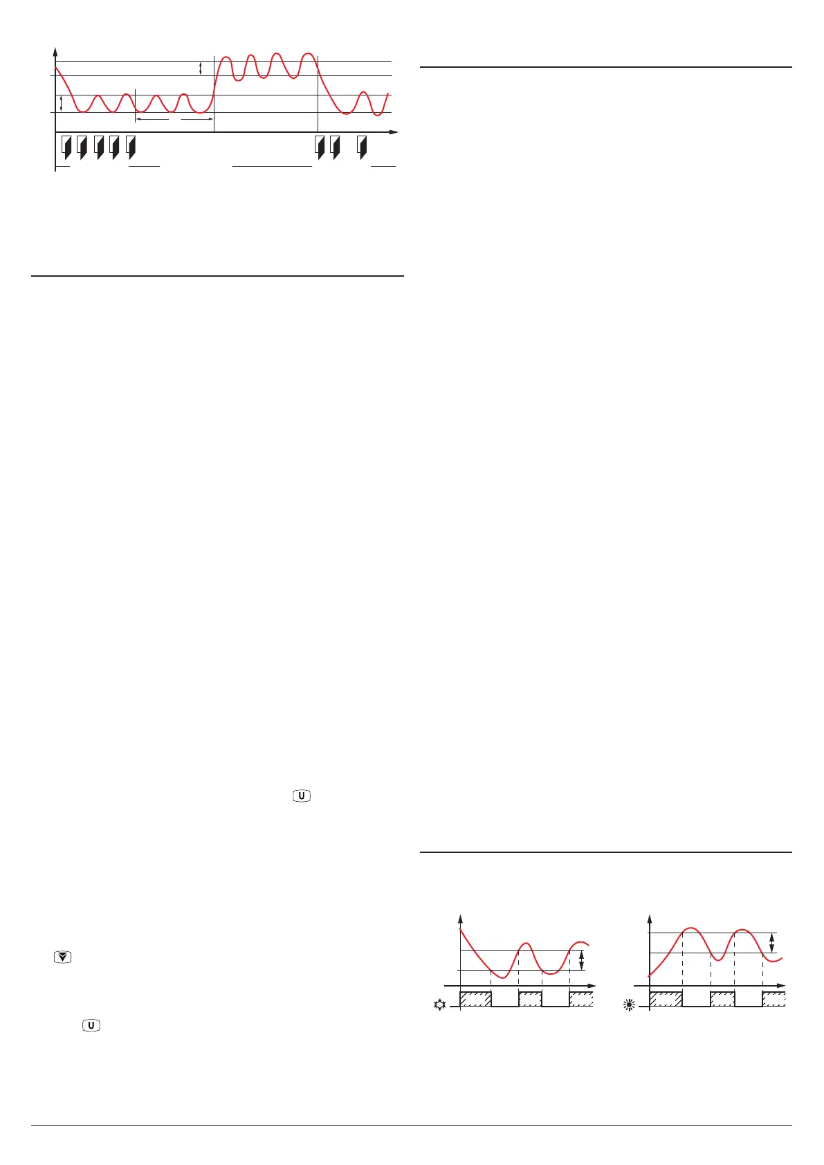
Temp.
SPE
SP
Door
rd
rEd
iEt
time
“Norm.”
DAY (Shop open) DAY (Shop open)NIGHT (Shop closed)
“Norm.” “ECO”
Pr1
Note: In the following examples the Set point is generally
indicated as SP and the differential as rd however the
instrument will act according to the Set Point and the
differential selected as active.
5.3 Measure and display configuration
With the iuP it is possible to select the temperature engi-
neering unit and the desired measure resolution (C0 = °C/1°;
C1 = °C/0.1°; F0 = °F/1°; F1 = °F/0.1°).
The instrument allows the measure calibration, which can
be used to recalibrate the instrument according to applica-
tion needs, The calibration is made by using parameters iC1
(input Pr1) and iC2 (Pr2 input).
Parameter iP2 allows to select the instrument usage of Pr2
measure as:
Au Auxiliary probe;
DG Digital Input (see the Digital input functions).
If Pr2 input is not used, set iP2 = oF.
Using iFt parameter can be set a software filter for the
measuring the input values in order to decrease the sensibility
to rapid temperature changes (increasing the sampling time).
Through the idS parameter is possible to set the variable
normally displayed:
P1: Pr1 probe measurement;
P2: Pr2 probe measurement;
SP: Active Set Point;
EC: Probe measure if the instrument is in Normal Mode,
the label Eco if the instrument is in (Eco mode);
OFF: If the numerical display must be switched off (oF).
When is displayed one of the measures idS = P1/P2/Ec the
iCU parameter allows to set an offset that is to be applied
only to the displayed variable (all controls will always happen
according to the correct temperature value, changed only by
the calibration parameters).
Regardless of what is set at idS parameter, all the measure-
ment variables can be shown pressing the key.
The display alternately shows the code that identifies the
variable (see below) and its value. The variables are:
Pr1 Probe 1 measurement;
Pr2
Probe 2 measurement (on/oFF if Pr2 is a Digital input);
Lt Minimum stored Pr1 temperature;
Ht Maximum stored Pr1 temperature.
The peak (min./max.) temperature values of Pr1 probe are
not stored in case of power failure and can be reset pressing
the for 3 s elapsed which, the display shows “---” for an
instant to indicate that the min./max. values have been erased
and the new peak is the temperature read in that moment
The system exits the variable dosplay mode after 15 s from
the last
key pressure.
It is also noted that the Pr1 probe display can also be changed
by defrost display function via the ddL parameter
(see the Defrost function).
5.4 Digital input configuration
The digital input function is defined using the iFi parameter
and the action is delayed for the time programmed with pa-
rameter iti. The iFi parameter can be configured for the
following functions:
0. Digital input not active;
1. Cell door opening with NO contact: at input closure (and
after the iti) the instrument displays alternately oP and
the variable set at idS parameter With this mode of
operation of the digital input activates also the time set
with parameter AoA elapsed which the alarm is activated
to warn that the door has been left open. In addition, at
door opening, the instrument returns to normal operation
if it was in Eco mode and the Eco mode activation was
enabled through parameter iEt
2. Similar to iFi = 1;
3. Cell door opening with output lock and NO contact: simi-
lar to iFi = 1 but with output lock. At alarm door open
intervention AoA also the output is re-activated.
4. External alarm signal with NO contact: at input closing
(and after the iti time) the alarm is activated and the
instrument alternately shows on the display: AL and the
variable set with parameter idS;
5. External alarm signal with Control output disabled and
NO contact: at input closing (and after the iti time) the
control output is is disabled, the alarm is activated and
the instrument shows on the display alternatively AL and
the variable set with parameter ids;
6. Normal/Economic mode selection with NO contact: at input
closing (and after the iti time) the instrument switches
to Economic operation mode. Opening the digital input,
the instrument returns in Normal operation mode.
7. Instrument On/Off (stand-by) selection with NO contact:
at input closing (and after the iti time) the instrument
is switched ON while it is placed in Stand-by mode when
the digital input is open;
8. Do not use;
9. Defrost activation command with NO contact: at input
closing (and after the iti time) the instrument starts a
defrost cycle;
10. End-Defrost command with NO contact: at input closing
(and after the iti time), if the defrost cycle is in progress
the instrument stops it, otherwise inhibits the defrost start;
-1... -10 - Features identical to the above but obtained
through a NC contact and a reversed logic operation.
5.5 Temperature control
The instrument control is ON/OFF and acts on the output
depending on the PR1 probe measuring, the Set Point SP (or
SPE), the Histeresys rd (or rEd) and the function mode rHC.
OUT (ot) OUT (ot)
SP
rd
time
offoff
SP
rd
time
ON
rHC =
rHC =
offoffON ON ON ON ON
Pr1
Pr1
Depending on the function mode programmed with parameter
rHC the differential is automatically considered by the control-
ler with positive values for a Refrigeration control (rHC = C)
or negative values for a Heating control (rHC = H).
In the event of a probe error, it is possible to set the instru-
 Loading...


