Do you have a question about the ascon M1 line and is the answer not in the manual?
General safety and electromagnetic compatibility guidelines for the controller.
Overview of the controller's installation requirements and safety precautions.
Specifications for the physical dimensions of the controller.
Required panel opening size for controller installation.
Operating conditions, special conditions, and forbidden environments for the controller.
Procedures for inserting the instrument into the panel.
Procedures for using mounting clamps to secure the instrument.
Procedures for removing the mounting clamps.
Procedures for unplugging the instrument.
Details of the terminal block layout and connection points.
Recommended practices for safe and effective electrical wiring.
Illustrative wiring diagrams for various controller functions.
Information on the controller's power supply voltage and consumption.
Details on OP1 output types (Relay, Triac).
Details on OP2 output types (SSR, Relay).
Configuration for the OP4 PV retransmission output.
Details on connecting and configuring serial communication interfaces.
How to connect various sensor inputs (thermocouple, RTD, mA, mV).
Information found on the instrument label and basic coding structure.
Detailed explanation of the product model code for hardware configuration.
Understanding the 4-digit code for controller settings.
Specifies the types and functions for the second alarm.
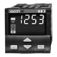
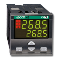
How to use the keypad and understand the controller display.
Navigating the display to view operational data and configuration.
Procedures for setting parameters using numeric or mnemonic input.
Managing keypad and output lock/unlock features.
Comprehensive guide to setting 1st group control parameters like PID, hysteresis.
Steps for configuring the controller using a 4-digit code and other settings.
How to start, stop, and understand the Fuzzy Tuning process.
Explanation of Step Response and Natural Frequency tuning methods.
Overview of controller features and technical details for PV inputs.
Details on operating modes, control algorithms, and output capabilities.
Specifications for setpoints, retransmission, safety, approvals, and physical dimensions.
Details regarding the product's warranty period and conditions.
Explanation of icons used for inputs, outputs, and special functions.
| Communication | RS485 (Modbus RTU) |
|---|---|
| Control Algorithm | PID, On/Off |
| Mounting | Panel mount |
| Input Type | Thermocouple, RTD |
| Output Type | Relay, SSR |
| Display | LED |
| Power Supply | 100-240VAC, 24VAC/DC |
| Alarm Output | Relay |
| Dimensions | 48x48mm, 48x96mm, 96x96mm |
| Control Mode | PID |