AC25/30QTP-1 and -3 Operations Manual.... 26
5.2 ELECTRICAL INSTALLATION, cont.
5.2.4 Multi-Cabinet Connections
Multi-cabinet systems should have each cabinet’s output connections paralleled at the switchgear
panel. The converters’ terminal blocks are sized for a single, appropriated sized cable per phase,
neutral, and grounding conductor.
Multi-cabinet systems are constructed from one cabinet which serves as the system Master, and a
second cabinet which serves as the Slave. A paralleling cable assembly (P/N 604650) is shipped
pre-installed in the Master cabinet. A paralleling cable assembly (P/N 604651) is shipped pre-
installed in the Slave cabinet and coiled at the base of the cabinet near the Input and Output
connection terminal blocks. This cable must be connected to the Master cabinet’s parallel port
located to the right of the output power connections.
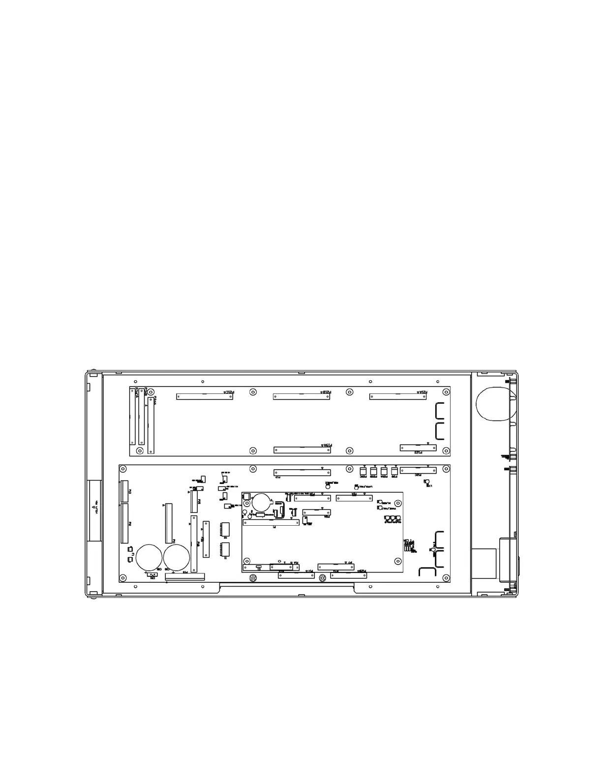
Figure 7: CONTROL MODULE CIRCUIT BOARDS
The Slave’s paralleling cable has a 6' standard length - do not substitute cable assemblies. If a
longer cable is needed for a given installation, contact the factory for the appropriate cable.