V2000 – Installation Guide
U-0623-0291.docx – Issue: 04 complete, approved
Page 12 of 40
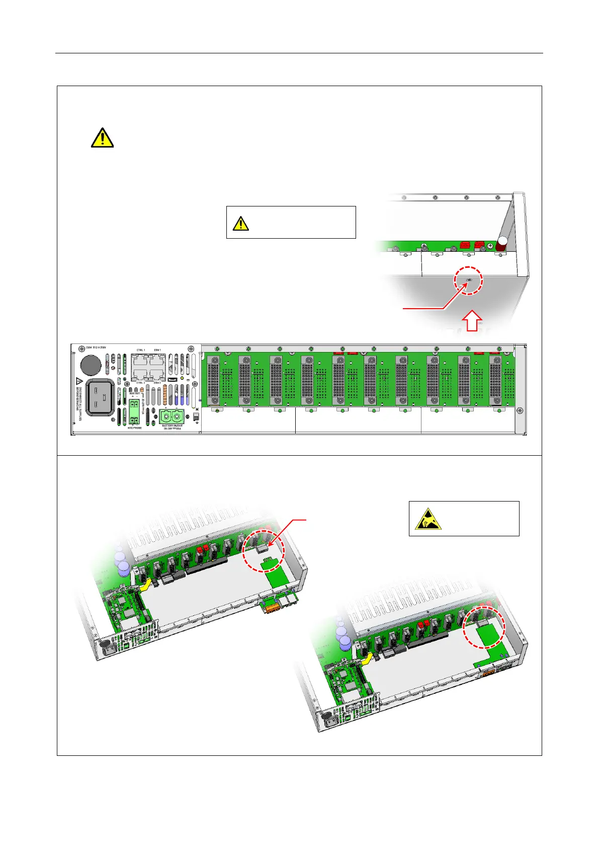
7. If used, fit one or two V2000-STBY Interface Cards to the rear panel standby interface card slots as
required by your system design.
If the mainframe is to be fitted with a single V2000-STBY Interface Card, the interface card
should be fitted into the right-hand side standby interface card slot as illustrated below.
a. Remove the Standby Blanking Plate by undoing 1 x screw at the bottom of the mainframe.
b. Insert the V2000-STBY Interface Card so that its rear connector mates the matching
connector on the backplane.
bottom of the mainframe.
countersunk
screw
Single V2000-STBY Interface Card
should be fitted into the right-hand
side standby interface card slot.
on the backplane.
Observe precautions for
handling electrostatic
sensitive devices.