V2000 – Installation Guide
U-0623-0291.docx – Issue: 04 complete, approved
Page 14 of 40
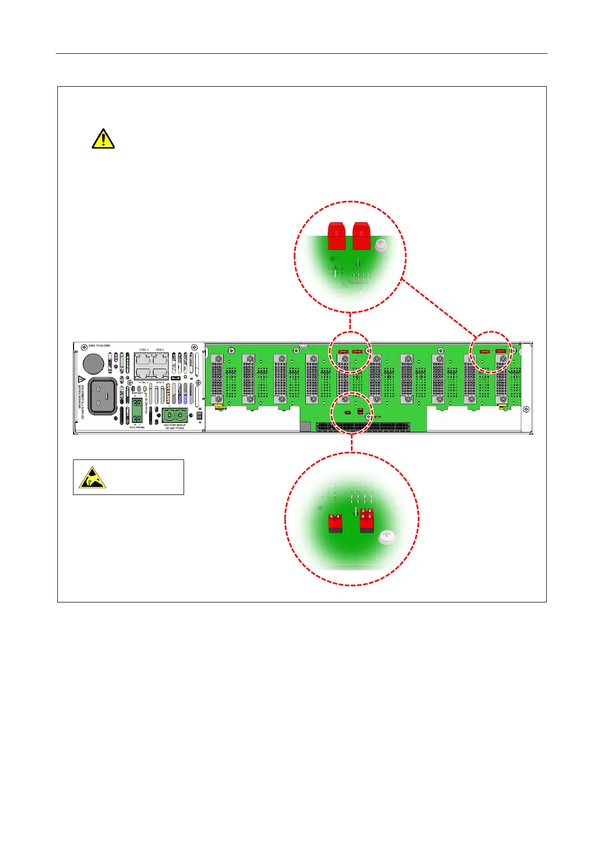
9. Set the standby links on the rear side of the backplane according to the number of V2000-STBY
Interface Cards fitted to the mainframe.
Ensure the standby links are correctly set on the V2000 backplane. If incorrectly set,
amplifiers may get damaged when a standby amplifier changes over.
a. No V2000-STBY Interface Card fitted: factory default link settings
Standard 2-way shortening link,
2.54 mm pitch
ASL PN 200028
(1 x 2.54 mm link)
2-pin shortening link,
5.08 mm pitch
(Harwin PN D3086-99)
ASL PN 208949
(4 x ‘handbag’ style links)
LINKS FITTED
(Top rear panel bar and bottom middle blanking plate not shown for clarity.)
Observe precautions for
handling electrostatic
sensitive devices.
LINKS FITTED