V2000 – Installation Guide
U-0623-0291.docx – Issue: 04 complete, approved
Page 23 of 40
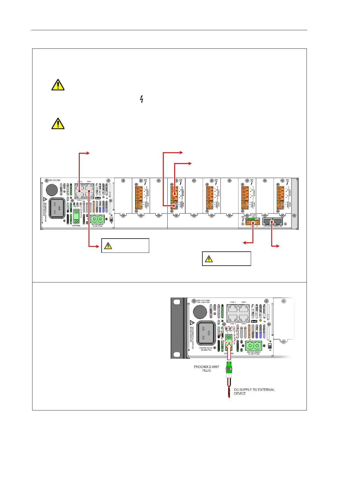
18. Connect the field wiring to the installed interface cards and control ports.
Refer to Section ‘6 Connections’ (page 26) for pinout details.
This equipment contains wiring that can be energised to 100 V RMS audio signals at up to
20 kHz.
Terminals marked with the symbol are hazardous, and the external wiring connected to
these terminals requires installation by instructed personnel.
The Ethernet cables should not be connected to the V2000 until system commissioning as
all V2000 units are supplied with same IP settings (factory default).
19. If used, connect the auxiliary DC power
supply cable to the rear panel connector
AUX OUT.
a. If required, cut the cable pair to
length and terminate it with a suitable
ferrule.
b. Terminate the cable with a Phoenix
2-way plug noting the correct polarity:
3.81 mm pitch plug (Phoenix MC
1,5/2-ST-3,81 – PN 1803578)
c. Ensure that the power cable is tied
neatly and clear from any sharp
edges or other risk of chafing.
LEVEL
STANDBY
STANDBY
INPUT
Ethernet cables.
preserved.