Do you have a question about the Assa Abloy 6200 Series and is the answer not in the manual?
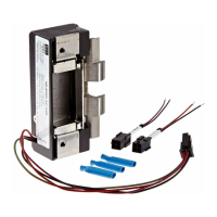
Details on system components, power, and device installation steps for function and monitors.
Step-by-step guide for installing the device, connecting wires, and testing system operation.
Important warnings regarding lead exposure and modifications to fire-rated openings.
Identifies common problems with exit devices and lists corresponding solutions.
Provides wiring connections for B, O, and S monitor types as per system schematic.
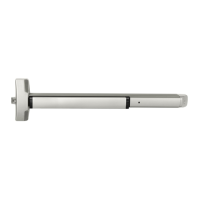
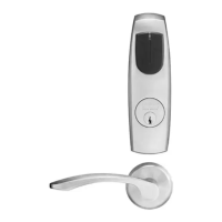
The 6100 / 6200 Series Exit Devices with Electric Dogging are designed to provide secure and controlled egress, integrating seamlessly with access control systems. These devices are part of the ASSA ABLOY ACCENTRA™ brand, emphasizing a commitment to safety and an open world through reliable hardware.
At its core, this exit device series offers electric dogging, a feature that allows the latchbolt to be held in a retracted (unlocked) position electronically. This functionality is crucial for applications requiring free egress during specific periods, such as business hours, without compromising security at other times. The system operates in conjunction with a 782 Controller, which manages the electric dogging function based on inputs from controlling switches. When the controlling switch closes contacts, the bolt retracts, enabling free passage. Conversely, when the switch contacts open, the bolt extends, securing the door. This controlled operation ensures that the device status corresponds directly to the switch contact status, providing clear and immediate feedback on the door's security state.
The device is designed for integration into a broader system, utilizing peripheral components such as Power Transfer Hinges and raceways to facilitate electrical connections. The integral power supply within the 782 Controller simplifies wiring by consolidating power inputs from the Power Transfer Hinge, controlling switch console, and the main 120 VAC power source. This centralized power management streamlines installation and ensures reliable operation.
For installations involving multiple exit devices on a single door or within a coordinated system, the 782 Controller supports connecting a second device to DEV 2, allowing for synchronized electric dogging across multiple points of egress. This capability is particularly useful in wide openings or double-door configurations where consistent security and egress functionality are required.
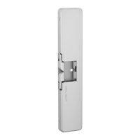
The system also supports optional monitoring features, providing valuable feedback on the door's status. These monitors can indicate egress in progress (B Monitor), whether the door is open from the outside (O Monitor), and whether the bolt is extended or retracted (S Monitor). This comprehensive monitoring capability enhances situational awareness and can be integrated into building management or security systems for real-time status updates.
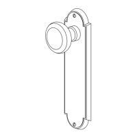
The 6100 / 6200 Series exit devices are designed for intuitive and reliable use. The electric dogging feature allows for convenient hands-free operation during peak traffic times, improving flow and accessibility. Users can actuate the device by pressing the touchbar or using the trim, ensuring easy egress when the electric dogging is disengaged. The smooth operation of the door and device, along with secure closing, is a fundamental aspect of its design, contributing to both safety and user satisfaction.
The system's adaptability to various door configurations is a key usage feature. The installation instructions detail how to prepare the door for wiring access, ensuring a clean and secure integration of electrical components. The requirement for clear channel access for wire connection highlights the importance of proper installation to maintain the device's functionality and aesthetic.
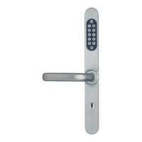
The ability to connect to external controlling switches provides flexibility in how the electric dogging is managed. These switches can be part of an access control system, a timer, or a manual override, allowing building occupants or administrators to dictate when the door should be secured or open for free passage. The adjustable delay feature of the 782 Controller, which keeps the electric latch retracted even when the controlling switch is open, offers an additional layer of control, preventing immediate re-locking and allowing for smooth passage through the opening. This feature is particularly useful in scenarios where a brief delay in re-securing the door is beneficial.
The monitoring options further enhance the usability of the system by providing critical information. The B Monitor, with its touchbar-actuated SPDT switch, signals when egress is in progress, which can be used for alarm activation or traffic counting. The O Monitor, a device-actuated SPDT switch, indicates if the door is open from the outside, useful for security surveillance. The S Monitor, a slider-actuated SPDT switch, provides direct feedback on the bolt's position (extended or retracted), confirming the door's locked or unlocked state. These monitoring capabilities are invaluable for security personnel and building managers, offering a comprehensive overview of door activity.
While the manual primarily focuses on installation, it implicitly highlights several aspects that contribute to the maintainability and longevity of the device. The emphasis on proper wiring and connections, including specific wire gauges for different lengths, is crucial for preventing electrical issues and ensuring consistent performance. Adhering to these guidelines during installation minimizes the need for future troubleshooting related to power delivery or signal integrity.
The troubleshooting guide provided in the manual is a vital maintenance feature. It offers a structured approach to diagnosing and resolving common problems, such as the device not working, sluggish bolt retraction, or intermittent action. By outlining a sequence of solutions, from checking remote switches and circuit continuity to inspecting wiring and foreign materials, the guide empowers installers and maintenance personnel to efficiently identify and rectify issues. This systematic approach reduces downtime and ensures the device remains operational.
The design's consideration for clear channel access for wire connection during installation also aids in future maintenance. Should wiring need to be inspected or replaced, the initial preparation of the door ensures that these components are accessible, simplifying repair work. The instruction to check for foreign materials and ensure the device is free from obstructions underscores the importance of a clean operating environment, which is a simple yet effective maintenance practice to prevent mechanical failures.
Furthermore, the warning regarding field modifications to fire-rated openings emphasizes the importance of consulting with code specialists and local officials. This proactive approach to compliance not only ensures safety but also prevents potential issues that could arise from unauthorized modifications, which might lead to costly repairs or replacements. By adhering to these guidelines, the long-term integrity and performance of the exit device are preserved. The robust construction and integration with reliable peripheral components, such as Power Transfer Hinges, are designed for durability, reducing the frequency of maintenance interventions. The clear instructions for initial setup and the comprehensive troubleshooting steps collectively contribute to a device that is not only functional but also manageable throughout its operational life.
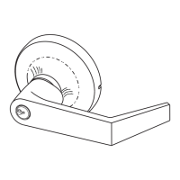
| Series | 6200 |
|---|---|
| Type | Mortise |
| Grade | 1 |
| Backset | 2-3/4" |
| Door Thickness | 1-3/4" to 2-1/4" |
| Finish | Various |
| Strike | Heavy-duty |
| Handing | Reversible |
| Function | Passage, Privacy, Classroom, Storeroom |
| Construction | Heavy-duty |