5 80-0180-418, Rev D
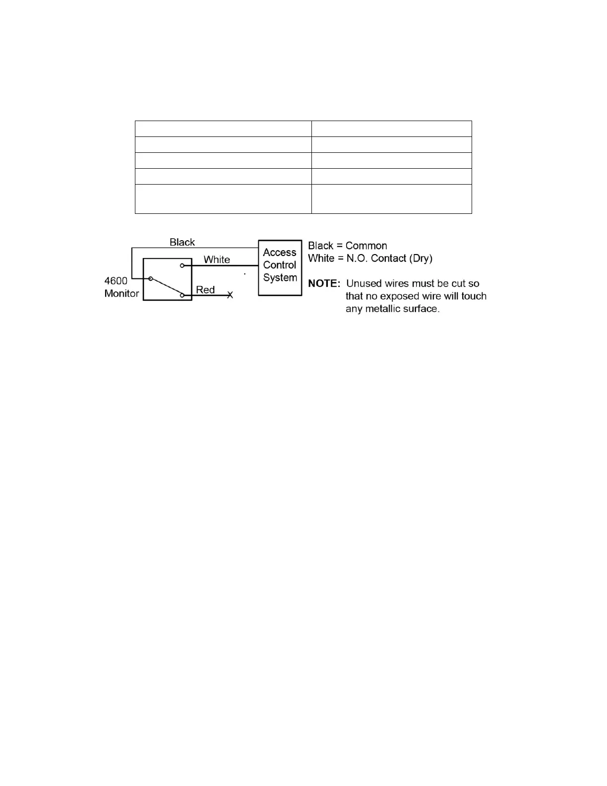
1. WIRE the optional monitor switch in accordance with Table 1, “Wire Colors and Maximum
Switching Current,” and Figure 5, “Example Wiring Diagram with N.O. Monitoring.”
Table 1. Wire Colors and Maximum Switching Current
Wire Color Label
Black Common Contact
White Normally Open Contact (N.O.)
Red Normally Closed Contact (N.C.)
Maximum Switching Current
(choose N.O. or N.C. for monitoring)
0.1A at 125 VAC/30 VDC
Figure 5. Example Wiring Diagram with N.O. Monitoring
Installing Trim to Stile
1. INSTALL rivnuts.
2. INSTALL the 4581 Cam Plug into the 4300, 4500, or 4900 deadlatch, and SECURE with the
set screw on the latch.
3. INSERT the drive spindle into the trim body prior to mounting.
4. MOUNT the cover plate (not required for 1-1/2” backset) and the trim body to the stile using
two #10-32 x 7/8” flat head screws.
5. SLIDE the cover onto the trim body from the top.
NOTE: The groove on the shaft faces opposite to the latch bolt.
6. INSERT the shaft through the hole on the cover and the output on the trim body.
7. TIGHTEN the set screw with a 3/32” Allen wrench to secure the shaft (see Figure 6,
“Installing Trim to Stile”).
8. INSTALL the top cap using two #4-40 x 1/4” flat head screws (see Figure 6).
9. PUSH the cover up flush with the top cap, and INSTALL the bottom cap using a #6-32 x 1/4”
flat head screw (see Figure 6).
 Loading...