17
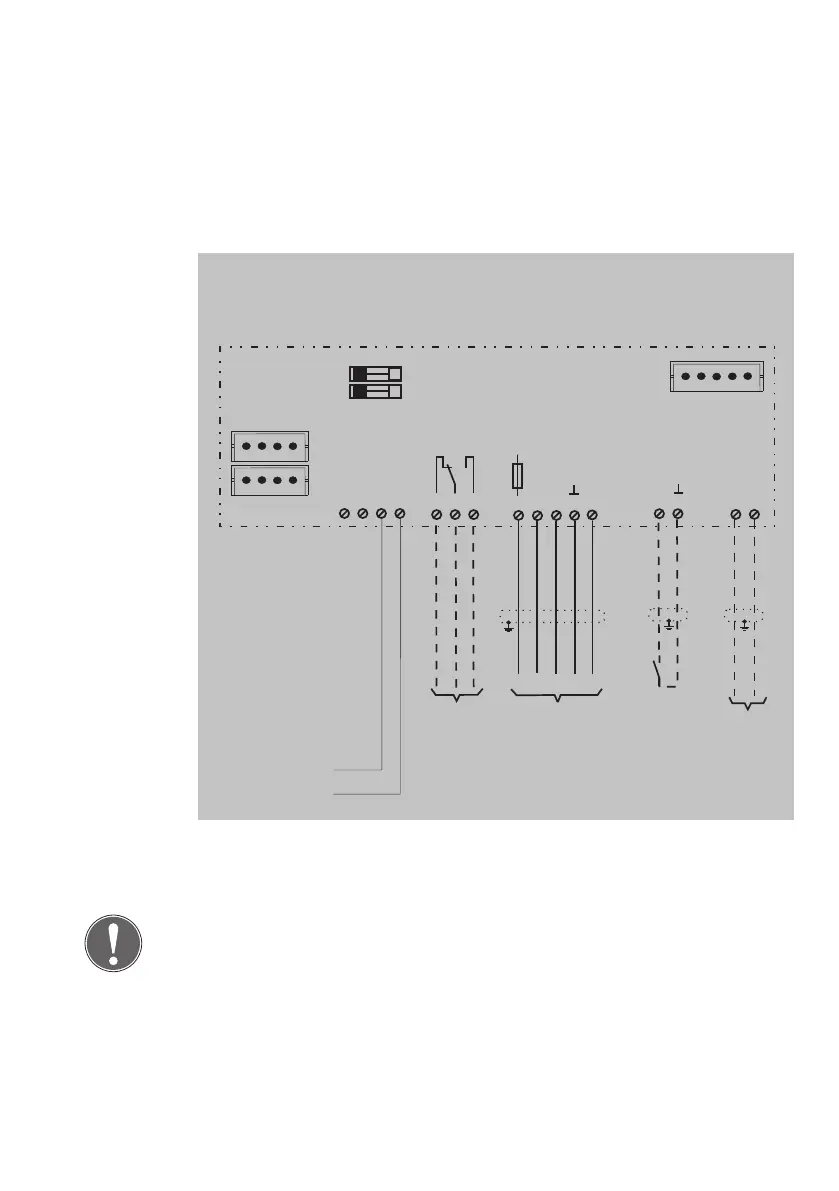
Circuit diagram
1)
Connections have different functions depending on the configuration
(see the ‚Configuration‘ section).
Additional information
The factory setting for the participant address is 1 for escape door modu-
le 1383E1N / 1383E2N.
A different participant address is only necessary in special cases. This can
be set manually with the key switch. The procedure is described in the
chapter Configuration - Change TSB address.
1383E1N = ASSA ABLOY Interface protocol FT1
1383E2N = ASSA ABLOY Device Protocol AADP
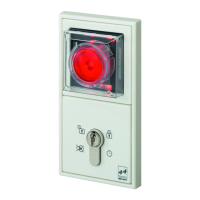
Individual es-
cape door mo-
dule
1383E1N
RS485 +
RS485 −
RS485
F1
Littelfuse
154001
1AF
2
1
3
4
5
6
7
8
9
11
12
10
13
14
15
16
AB E
D F
S
LB1
LB2
Voltage supply via an
external mains adapter
12 - 24 VDC +15% / -10%
according to DIN/EN
60950
Connection of the
respective locking
part
SYSCON-5
SYSCON-4
Jumpers LB1/LB2
5-pin system plug connector for
connection of the type 1385ES1
key switch or additional
components
max. 24V / 1A
2 x 4-pin system plug
connector for
connection of the mains
adapter type
1003FT-24-05 and/or
additional system
components
Potential-free
relay contact
1)
Universal
input
1)
+
-
See manual D00470..