25
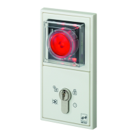
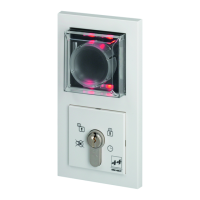
Device
1385
can be extended with E/A Extension Module 901-20 to
include further switching operations.
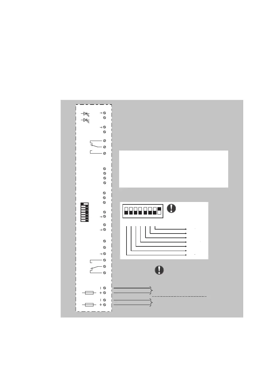
Circuit diagram
I/O extension
module 901-20
12
3
4
56
7
8910
11 12
13
14
15 16
17
18 19 20
21 22
23
24
25 26
27
28
1234567 8
ON
OFF
F1
0,5AT
F2
0,5AT
K2
Potential-free relay contact
max. load capacity 24V/2A
Potential-free relay contact
max. load capacity 24V/2A
Coding switch for setting
bus address of the device
K1
D
Green
LED
Yellow
LED
E1 E2
E3 E4
E5 E6
E7
E8
A1 A2
A3
A4
12 V battery or 12 V DC, regulated
12 V DC ±10 %, max. residual ripple 50 %
12 V AC ±10 %
Only at terminal 1 and 2: 24 V DC, regulated
ON
123
45
6
7
8
2
0
2
1
2
2
2
3
2
4
2
5
2
6
64
32
16
8
4
2
1
Switch 8 must
be set to ON.
Power supply
E1-E8 = inputs / signal = low active (0V)
A1-A4 = outputs - open collector / earth switching (0V)
(observe voltage drop!)
K1 = potential-free relay output
max. load capacity 24V / 2A (ohmic load)
K2 = potential-free relay output
max. load capacity 24V / 2A (ohmic load)
Note:
Only one power supply
may be connected.


 To Next Page