24
Connection of connecting line SYSCON4 or SYSCON5 to permanent
wiring.
Additional information
Do not use SYSCON4 and SYSCON5 together at the same time.
An external switch contact (control element) is connected in accordance
with the use specifications table.
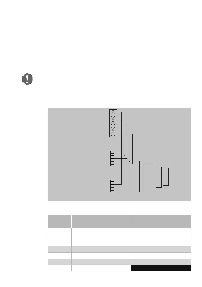
Circuit diagram
Terminal assignment
Screw
terminal
SYSCON 5 SYSCON 4
1 +12 V DC – +24 V DC
corresponding to the vol-
tage supply
+12 V DC – +24 V DC
corresponding to the vol-
tage supply
2 0 V CAN-H
3 Key switch, left CAN-L
4 Key switch, right 0 V
5 Tampering contact
Adapter circuit
board 1385EAP
1
2
3
4
5
1
2
3
4
5
1
2
3
4
5
1
2
3
4
5-pin
5-pin connecting
terminal
5-pin type 086 RIA
Circuit board layout
SYSCON5
SYSCON5
SYSCON4
SYSCON4