Raising the Standards
An ASSA ABLOY Group company
3
Electrical ratings for the 5000:
What faceplate will you be using?
501
501A
503
502
504
501B
503B
metal
metal
flat aluminum
flat aluminum/wood
wood
aluminum door
aluminum door
501
501A
503
502
504
501B
503B
option
door/frame
pg 24
pg 24
pg 18
pg 26
pg 21
pg 16
pg 14
Step 1
Step 2
Minimum Wire
Gauge Requirements
Solenoid Voltage
12V - 16V
24V
200 feet or less
18 gauge
20 gauge
200 to 300 feet
16 gauge
18 gauge
300 to 400 feet
14 gauge
16 gauge
Refer to pages 13-26 for faceplate dimensions.
strike wiring
configuration
continuous duty
intermittent duty
12V - 16V 24V
resistance
50 Ohms
200 Ohms
10.8 VDC - 17.6 VDC
12 VAC - 17.6 VAC
10% max duty cycle. (2 minute max on time).
10.8VDC - 13.2VDC
.22 Amps - .27 Amps
.22 Amps - .35 Amps
24 VAC - 26.4 VAC
.12 Amps - .13 Amps
21.6 VDC - 26.4 VDC
.1 Amps - .13 Amps
21.6 VDC - 26.4 VDC
.1 Amps - .13 Amps
.24 Amps - .35 Amps
4
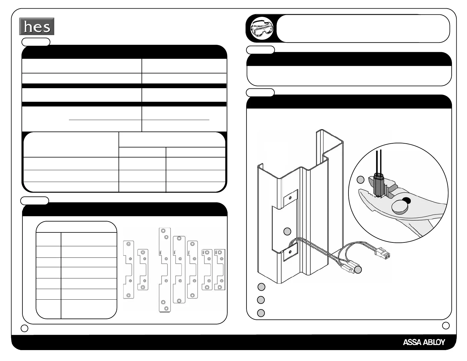
Installer Hint
The wires do not need to be stripped, insert wires into the blue wire
connector, crimp with pliers, and you are finished.
Is your frame already prepared?
If the answer is yes continue to step 4.
If the answer is no see frame prep example pages 11-12.
Is a pigtail already attached?
Step 3
Step 4
If the answer is yes continue to step 5.
If the answer is no please follow the instructions below.
Retrieve wires from inside the frame.
a
Connect the pigtail to the wires inside the frame by using the
blue wire connectors.
b
Crimp connectors with pliers.
c
a
b
c
 Loading...