7
A7113E • 800-810-WIRE (9473) • www.sargentlock.com
Keypad 10 Line Lock
8/14/08 Copyright © 2005, 2007,2008, SARGENT Manufacturing, an ASSA ABLOY Group company. All rights reserved.
Reproduction in whole or in part without the express written permission of SARGENT Manufacturing is prohibited.
Screws partially
tightened
For wood
door only
Inside
of door
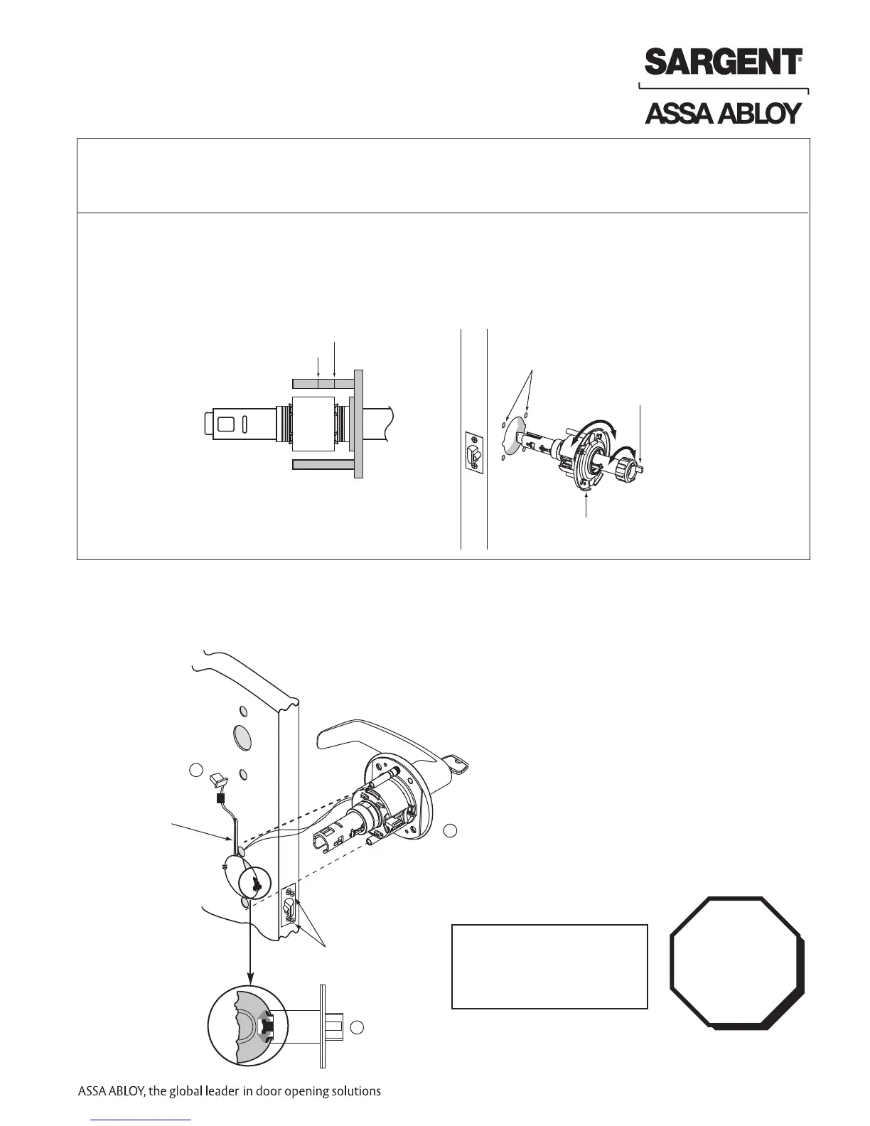
1
2
Lock Preset to:
• Through-bolt location– 12 & 6 o'clock
• Door thickness– 1-3/4" thick- see below for other door conditions
Adjustment for different through-bolt and door thickness:
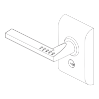
• Remove outside lever (usually keyed), scalp and spacer bushing
• Rotate mounting plate to either align with through-bolt holes in door,
or adjust for proper door thicknesses (see markings on through-bolt)
• Reinstall spacer bushing (to align with back of lever) scalp and lever
Step #5 Lock Installation
IMPORTANT:
Door must remain open
during installation.
Use door stop.
1-3/4" thick door
2" thick door
T
hrough-bolt
holes
Rotate to match
through-bolt holes in door
Spacer bushing
1. Feed wires into the lock body hole from outside of door
2. Install lock body into cross-bore hole from outside of the door (locked side)
3. Lock body must engage both the latch unit prongs and tail piece (as shown)
IMPORTANT:
Lockbody
must be
centered in
the door.
 Loading...