21
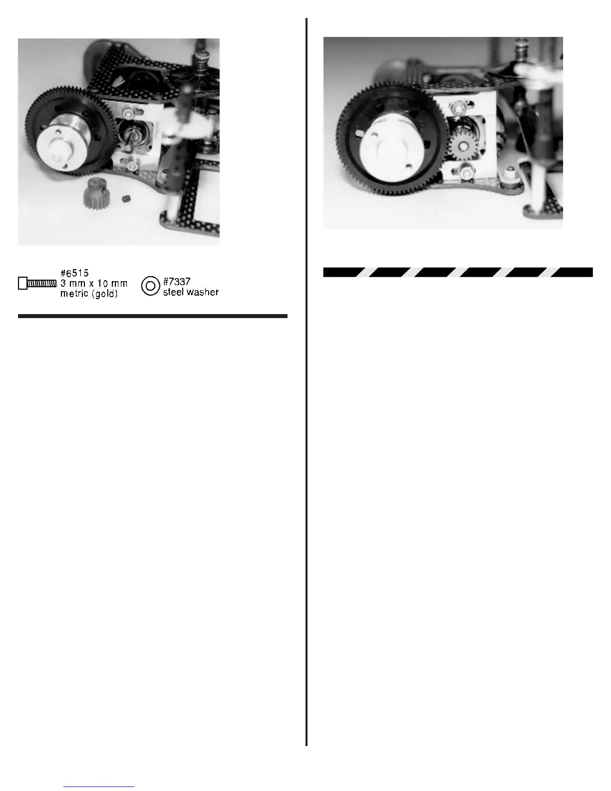
Fig. 73
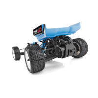
❑ Fig. 74 Now we need to set the gear mesh. This is
accomplished by moving the motor forward or back. This
moves the pinion gear closer to or further away from the spur
gear. What we want to accomplish is to get the metal pinion gear
as close to the spur gear as possible, but without binding the
gears. The easiest way to check this is to put your finger on the
nylon spur gear. See if you can rock the spur gear teeth back
and forth (lightly) between the pinion gear teeth without making
the pinion gear move. We want the gears meshed as close as
possible but still have the ability to rock the spur gear. When you
have the spacing correct you can tighten down the two #6515
3mm screws. Now recheck the gear mesh to make sure nothing
moved when you tightened down the screws. It is important to
keep in mind that a tight gear mesh will result in a high power
loss. A loose gear mesh can result in stripping off the spur gear
teeth. So take your time.
WARNING! The gold colored motor
screws are metric. The coloring was done to prevent
mixing up the motor screws with the standard black 4-40
screws used in the rest of the kit. Accidentally using the 4-
40 screws in the motor will strip out the mounting holes in
the motor can. This damage to the motor can cannot be
corrected except by replacing the motor.
Fig. 74
STEERING SERVO & TIE-ROD
ASSEMBLY
Most radio systems come with standard medium size
servos. Because of space limitations a medium servo will not
fit. The stock servo mounting holes will accept the following
servos that we have been able to test.
Airtronics Futaba
94143 S-32H/S-32SH
94144 S-132H/S132SH
94145 S-9601
94831
If you have a servo not listed here, make sure it fits
before you try to install it. Other servos may fit, but also may
require drilling new mounting holes in the chassis.
Note: We only supply one servo saver with the kit.
As a random choice we have included the Airtronics servo
saver. If you have a Futaba servo or other brand you will
have to purchase the correct servo saver.
❑ Figs. 75 & 76 Go back and take out bag #1 that we
set aside early in our assembly. From this bag remove the two
#8435 molded steering servo mounting blocks. The drawing
below shows which holes to use with the different size servos.
Now determine which mounting holes are correct for your
servo. Take out your drill motor and #43 drill bit. (Remember if
you could not find a #43 drill bit a 1/8” bit will work if you are very
careful). Drill the correct two holes in each mount for your servo.
Make sure the hole is perpendicular to the mounting face of the
servo mounting block.
Next remove the #3760 Airtronics servo saver, two
#4448 aluminum ball ends, and two #4449 4-40 small alumi-
num locknuts (also in bag #1). Please remember if you have a
Futaba or another brand of servo you will have to purchase the
correct servo saver. The photo shows the eight holes in the
servo saver. You will need to drill out the top two holes (one on
each side). We want the balls to be as close to the servo horn