22
pivot point as possible. Use your #34 drill bit, or your 3/32” if you
cannot find a #34 bit. After you have drilled out the holes install
the two #4448 ball ends into the servo saver and thread the two
#4449 locknuts onto the ends of the threads.
WARNING! The
ball ends should just be able to slide through without
threading. The holes are close enough to the edge of the
servo saver they could crack through if the ball ends were
threaded in.
Fig. 75
Fig. 76
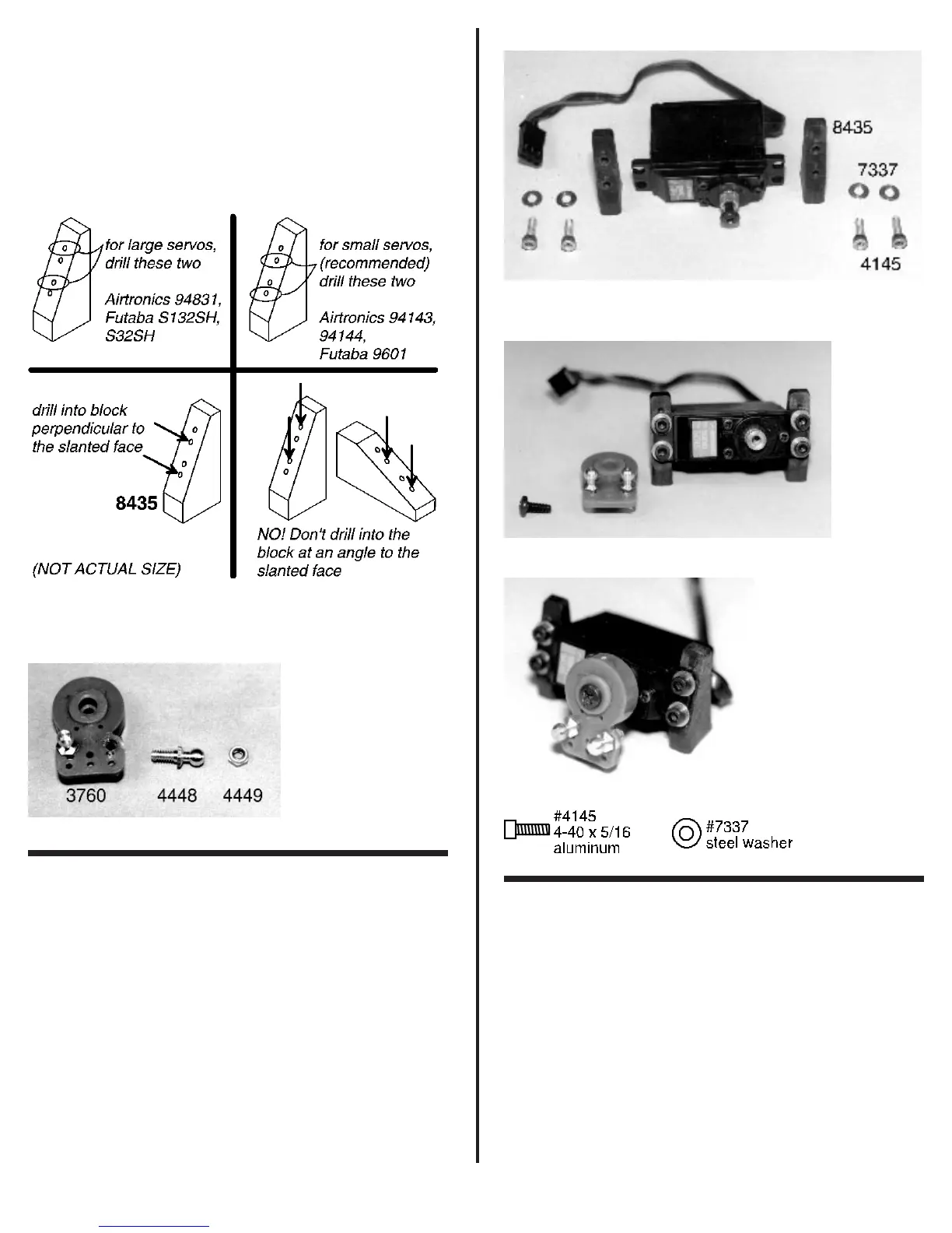
❑ Figs. 77, 78 & 79 Remove the four #4145 4-40
x 5/16” aluminum SHCScrews and four #7337 servo washers
(small gold colored) from bag #1. Use the #4145 screws and the
#7337 washers to secure the two #8435 servo mounting blocks
to the servo.
Now remove the stock servo horn, if one came on your
servo, and install the servo saver. We want the servo saver to
be pointing down. Now check the throw of the servo saver in
both directions. If it does not have the same travel in both
directions, remove the servo saver and rotate it's starting
position one or more splines and then reinstall it. Go ahead and
secure the servo saver with the stock servo horn screw (for
metal gear servos) or the screw that came with the servo saver.
With the servo output shaft facing you, make sure the output
shaft it to your right side. Your completed servo should look like
fig. 79.
Fig. 77
Fig. 78
Fig. 79
❑ Fig. 80 In bag #1 you will find two #6292 4-40 x 3/8”
FHSScrews. We will use these to secure the servo mounts to
the chassis. The holes for mounting the servo to the chassis are
spaced so that the most popular Airtronics or Futaba servos will
fit. You may have to adjust the placement of the #4145 screws
in the mounting locations but this is all that should be required.
If you are running a different brand of servo you may have to drill
new holes if the existing ones do not line up correctly. Use the
two #6292 screws to secure the servo to the chassis as shown.