23
Fig. 80
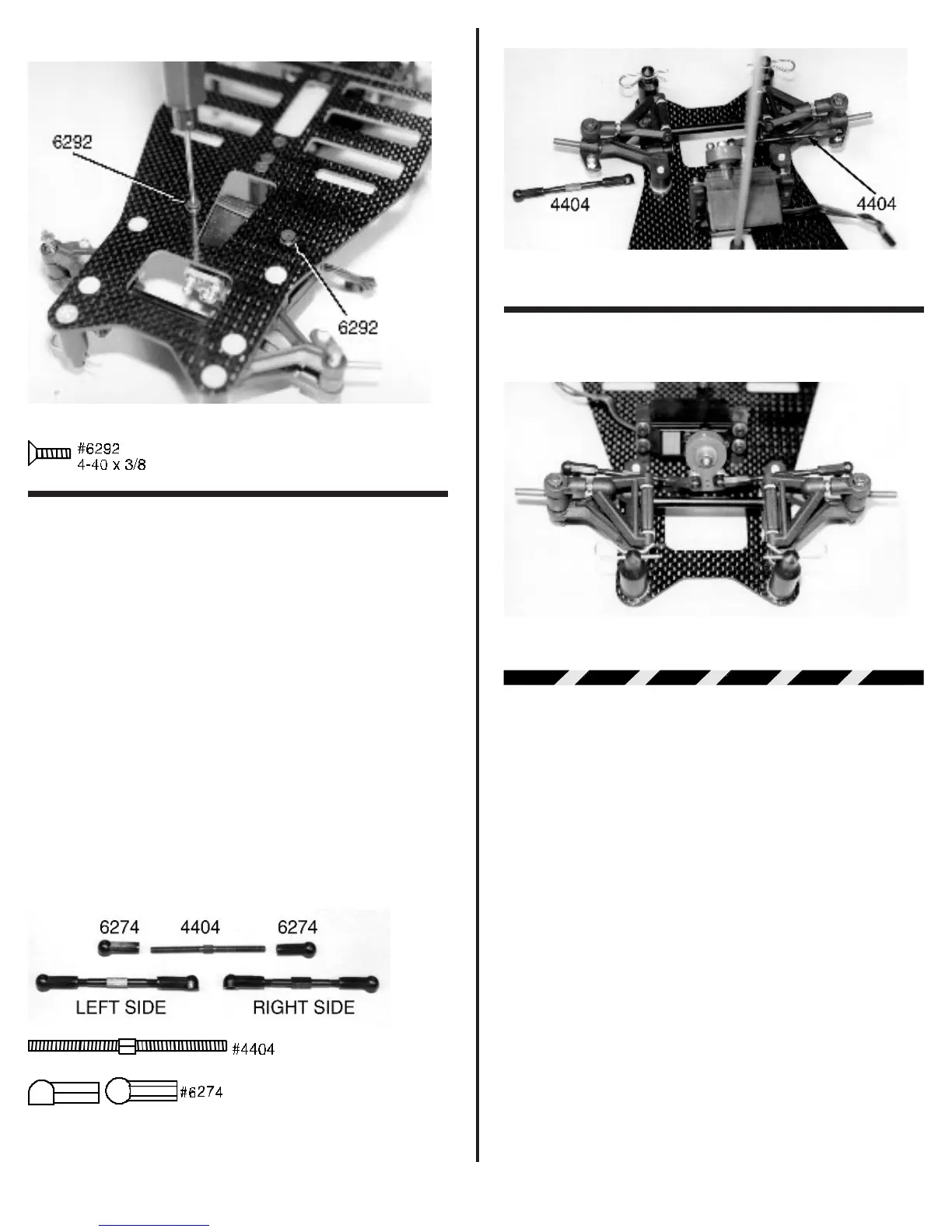
❑ Figs. 81 & 82 Now we need to take out the two
#4404 turnbuckles and four #6274 plastic ball end cups. Screw
one #6274 plastic ball end cup onto the end of each turnbuckle
evenly. The turnbuckles have left hand threads on one end and
right hand threads on the other end. This means the ball end
cups will thread on in opposite directions. Adjust the ball end
cups until you reach an adjusted length of about 2 3/16” (about
55.5mm or 2.18”). All measurements are done from the
center of the ball cup hole to the center of the opposite ball
cup hole. Because the servos may place the output shaft in
slightly different positions you will have to fine tune the front toe-
in after everything is installed. Notice the difference in the
direction the ball cups face on opposite ends of the same
turnbuckle. Also the right and left turnbuckles will be facing ins
opposite directions as shown in fig. 81.
Snap the assembled turnbuckles onto the steering
block ball ends and the servo saver ball ends. It will be best to
do this with your needlenose pliers. Remember there is a right
and a left hand turnbuckle. You can adjust the front toe-in now
or wait until the final adjustment section at the back of the
manual.
Fig. 81
Fig. 82
❑ Fig. 83 Your completed front suspension with steering
servo should look like this.
Fig. 83
BATTERY ASSEMBLY &
INSTALLATION
Your new RC12LC is setup to run four or six cell saddle
type battery packs. Some companies offer these in pre-as-
sembled packs but most people will have to assemble their
own. The following steps will show you the correct way to
assemble a six cell saddle type battery pack if you do not
already know how.
❑ Figs. 84 & 85 Make sure you use ROSIN core
solder, the preferred being the more popular 60/40 variety. DO
NOT use acid core solder. This can damage your electrical
components and connections. Fig. 84 shows the right or
passengers side of the battery pack. Fig. 85 shows the left or
drivers side view of the same battery pack. The cells are
soldered in series. This means the positive end of the first cell
will be soldered to the negative end of the second cell, and its
positive end be soldered to the negative end of the third cell and
so on. In between the third and fourth cell the connection will be
made by a jumper wire. This wire has to be long enough to reach
across the gap between the slots in the chassis and to be able
to clear the T-bar. Normally we use 16 or 14 gage wire for this
connection.