7
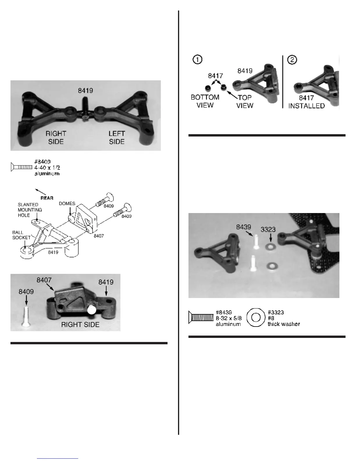
#8407 upper arm mounts. Place the upper arm mount against
the lower arm so the domes interlock. Make sure that the slant
is facing down and to the front as shown in the photo. Secure
the mount to the arm with two #8409 4-40 aluminum screws. Go
ahead and assemble the left arm and mount following the same
steps.
Note: be sure the Allen wrench is fully seated into the
socket of the #8409 aluminum FHMScrew. If the Allen wrench
is not all the way in it can cause the aluminum screw head to
strip out before it is completely installed.
Fig. 6
Fig. 7
Fig. 8
❑ Fig. 9 Also in bag #1 you will find a smaller bag
containing the four #8417 plastic pivot balls. We will remove two
for now. Look at the pivot ball. You will see that one side of the
ball has a shoulder. Before we install the pivot balls look closely
at the center hole from both sides. If you see any burrs remove
them with a sharp X-acto knife.
To properly install the ball in the lower arm we want the
shoulder facing up or on top. Place the pivot ball on the work
bench then place the lower front arm over the pivot ball. Now
snap the arm onto the ball using your thumb. This can take a fair
amount of effort to accomplish, so you can also place a ¼” nut
driver on the arm over the pivot ball and then use your hand to
impact the tool until it snaps into place. Note: always install
the pivot balls from the bottom of the lower front arm. We
do not recommend the use of pliers to install the pivot balls
since they can cause the balls to deform. Now go ahead and
install the second pivot ball into the left lower front arm.
Fig. 9
❑ Fig. 10 In bag #1 you will find four #8439 8-32 x 5/8”
FHMScrews and four #3323 #8 thick aluminum flat washers.
Line up the right arm assembly with the two matching holes on
the right front of the chassis. Install two #8439 screws through
the bottom of the chassis. Now place one #3323 aluminum
washer over each screws on top of the chassis as shown. Use
your #2 Phillips screwdriver to secure the arm to the chassis.
Do not completely tighten the screws just yet. Now repeat the
above steps to install the left arm assembly.
Fig. 10
❑ Figs. 11 & 12 Still working with bag #1 remove the
#4506 aluminum front suspension brace and two #6917 4-40 x
3/8” BHSScrews. Look closely at each of the upper arm
mounts. You will find a hole in each mount just above where the
mount attaches to the lower arm (see photo). Place the brace
tube between the arm mounts. Line each end up with the hole
in the mounts. Now secure the brace tube to the mounts using
the two #6917 screws. Go ahead and tighten the screws. Go
back to fig. 9 and tighten the four #8439 screws.