8
Fig. 11
Fig. 12
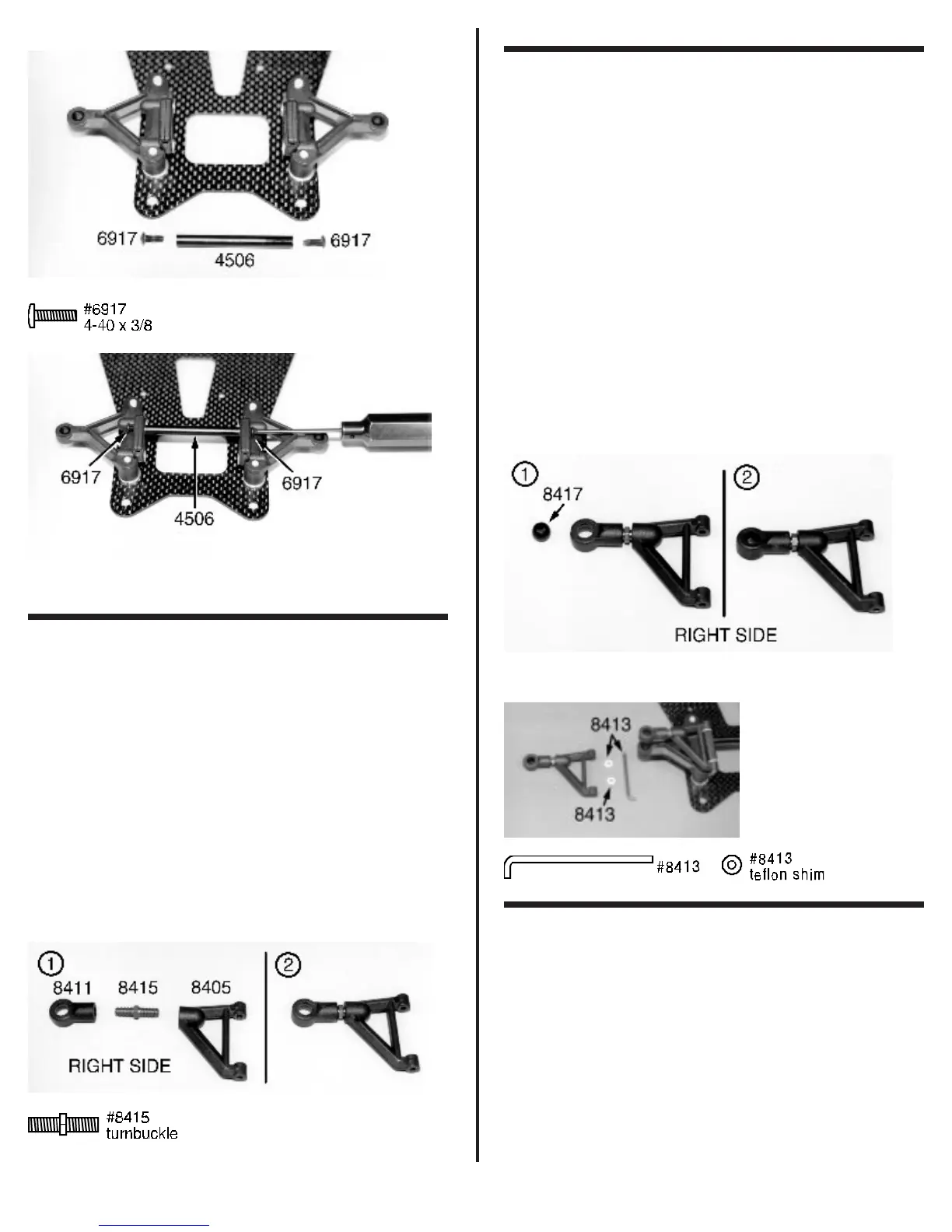
❑ Fig. 13 Remove two #8411 nylon upper arm eyelets,
two #8415 upper arm turnbuckles, and two #8405 upper
suspension arms. The upper suspension arms are the same
until they have been assembled. We are still working with bag
#1. Now we will start with the right side. Thread one of the #8411
nylon eyelets onto one end of the #8415 turnbuckle. Now hold
the center section of the turnbuckle with the #8416 wrench.
While holding the wrench, thread on one of the upper suspen-
sion arms until the threads bottom out.
The photo shows the right arm parts laid out and then
correctly assembled. Look at the outer edge of the upper arm
eyelet. On one side the outer edge is rounded and the other is
more sharp or square edged. Make sure the square edge is
facing down. Now assemble the left arm which will be a mirror
image of the right arm but make sure the sharp or square edge
of the eyelet is facing down as well.
Fig. 13
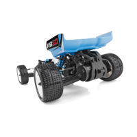
❑ Figs. 14 & 15 Remove the two remaining #8417
plastic pivot balls. Place one of the balls on the work bench
shoulder side down. Place the square edge side of the upper
arm eyelet over the pivot ball. Again use your thumb to snap the
eyelet onto the pivot ball. If you are having trouble doing this you
can use your ¼” nut driver to make the assembly easier. We do
not recommend using pliers for this installation.
Now locate the two #8413 upper arm hinge pins and
the small bag with the four #8413 PTFE caster shims that will
be in bag #1. We are going to install the right upper suspension
arm to the right arm mount. Make sure you have the right upper
arm by checking the eyelet to see that the square edge side is
down. Also make sure that the angled side of the arm is to the
front. Slide the #8413 upper arm hinge pin through the upper
arm and arm mount. Make sure one of the #8413 PTFE caster
shims is installed on each side of the arm mount. Go ahead and
install the left upper suspension arm.
Note: Changing the
location of the PTFE caster shims will give you different caster
settings. See tuning section at the end of the manual for more
details.
Fig. 14
Fig. 15
❑ Figs. 16 & 17 Next we need the #8421 nylon
steering blocks in bag #1. You will see a line molded into the
steering block between the two holes. This is the top side of the
steering block. The photo will show which is the right and left
steering blocks. The steering blocks were designed to fit both
our 1:12 and 1:10 scale cars. For the one 1:12 scale car we
need to cut the steering block at the mold line as shown. After
you have cut the steering blocks you will want to round the
corners where you cut. You can use your file or sandpaper to
accomplish this.