ASUS A7N8X motherboard user guide
9
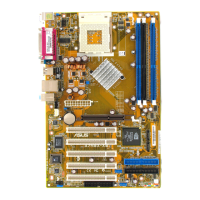
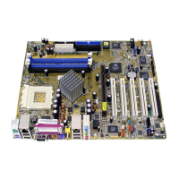
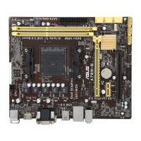
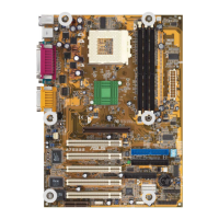
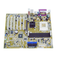
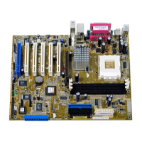
2.2 Layout contents
CPU, Memory and Expansion Slots
1) Socket 462 p. 11 CPU Support
2) DIMM 1/2/3 p. 13 System Memory Support
3) PCI 1/2/3/4/5 p. 15 32-bit PCI Bus Expansion Slots
4) AGP Pro 8x p. 18 Accelerated Graphics Slot
Motherboard Settings (Jumpers)
1) SATA_EN1 p. 19 Serial ATA Setting (3 pin)
2) KBPWR1 p. 19 Keyboard Wake Up (3 pin)
3) USBPWR12, 34, 56 p. 20 USB Device Wake-up (2x3 pin)
4) CLRTC1 p. 21 Clear RTC/CMOS RAM (3 Pin)
Connectors
1) PS2KBMS p. 22 PS/2 Mouse Port (6 pin female)
2) PS2KBMS p. 22 PS/2 Keyboard Port (6 pin female)
3) USB p. 23 Universal Serial Bus Ports 1 & 2 (2 x 4 pin female)
4) COM2 p. 23 Serial Port and Header (9 pin male, 10-1 pin male)
5) RJ45 p. 24 Fast-Ethernet Port Connector (4 pin) (Optional)
6) PRINTER p. 24 Parallel Port (25 pin female)
7) AUDIO p. 25 Audio Connectors (Six 1/8” jacks)
8) IDELED p. 25 IDE Activity LED (Two 40-1 pin)
9) FLOPPY p. 26 Floppy Disk Drive Connector (34-1 pin)
10) PRIMARY / SEC. IDE p. 26 IDE Connectors (2 x 40-1 pin)
11) PRI/SEC_SATA1 p. 27
SATA Serial ATA Connectors (2 x 7-pin)
12) IR_CON1 p. 27 ASUS Front Panel Audio Connector (10 pin)
13) CPU_FAN1 p. 28 CPU Fan Connector (3 pin)
14) 1394HEAD p. 28 IEEE-1394 Header (8-pin) (Optional)
15) ATXPWR p. 29 Power Supply Connectors (20 pin block)
16) SMB p. 29 SMBus Connector (6-1 pin)
17)
MODEM, CD_IN1, AUX
p. 30 Internal Audio Connectors (2 x 4 pin ) (Optional)
18) SPDIF1 p. 30 Digital Audio Interfaces (6 pin) (Optional)
19) USB_56 p. 31 USB Headers (10-1 pin)
20) PWRTMP1 p. 31
Power Supply Thermal Sensor (2-pin ) (Optional)
21) GAME p. 32 Game Connector (16-1 pin)
22) CHASSIS1 p. 32 Chassis Open Alarm Lead (4-1 pin)
23) FPAUDIO1 p. 33 Front Panel Audio (10-1 pin)
24) PWR_LED (Panel) p. 33 System Power LED Lead (3-1 pin )
25) KEYLOCK (Panel) p. 33 Keyboard Lock Switch Lead (2 pin )
26) SPEAKER (Panel) p. 33 System Warning Speaker Lead (4 pin )
27) SMI (Panel) p. 34 System Management Interrupt Lead (2 pin)
28) PWR (Panel) p. 34 ATX Power Switch / Soft-Off Switch Lead (2 pin)
29) RESET (Panel) p. 34 Reset Switch Lead (2 pin)
 Loading...