Rev. AX5 Draft Page 27
AdvanTag 9100 Technical Manual
Chapter 2: Theory of Operation
Interfaces
a
Long Range (9100 Reader only)
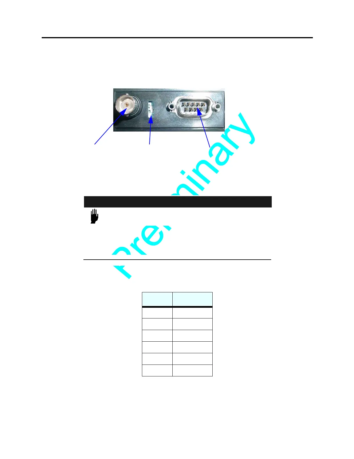
Located on the side of the unit (see Figure 6 on page 27), this dip switch controls the
read/write range of the antenna. When the switch is in the On position, the unit is in
Standard Range mode. When the switch is in the Off Position, the unit is in Long Range
mode (see “Antenna Performance” on page 30).
F
IGURE 6 Long Range Switch, AdvanTag 9100 Reader, Side View
Node Address (9100 Reader only)
CAUTION
THE NODE ADDRESS PANEL (SEE Figure 7 on page 28)
SHOULD ONLY BE ACCESSED BY QUALIFIED PERSONNEL.
F
AILURE TO COMPLY MAY RESULT IN MALFUNCTION OR
DAMAGE TO THE UNIT.
Used to specify the unit's address or TargetID. The switches represent powers of binary
digits:
The ON setting represents 1 and the OFF setting represents 0. For example, to set the
address to “15,” set switches 1, 2, 3, 4 ON and 5, 6 OFF. See Figure 7 on page 28.
Switch # Binary Digit
11
22
34
48
516
632
Antenna
Connector
CAN PWR
Connector
Long Range
Switch
 Loading...