Installation & Servicing instructions ATAG iR-Range
22
9.6 Flue gas exhaust system
Theuegasexhaustsystemandairsupplysystemconsistsof:
- Flue gas pipe;
- Air supply pipe;
- Roof or wall terminal.
Theuegasexhaustsystemandairsupplysystemmustcomplywith:
Theuegasoutletandairsupplyinstallationmustcomplywiththecurrentregulationrequirements.IGUP10
and BS 715.
The ATAG iR boiler as described in this manual is NOT suitable for a combined ue system.
Theapplianceconcentricconnectiondiameteris60/100mm,towhichtheuegasoutletandairsupply
systemcanbetted,withorwithoutelbowpieces.ThemaximumpermissiblepipelengthissetoutinTable
9.6.2.a.
Forfurtherinformationabouttheavailablecomponentsoftheuegasandairsupplysystemwerecommend
you consult the Flue system literature. Combinations with other brands or systems are, without written
permission from ATAG Heating, not permitted.
TheATAGuegassystemismeant,anddesigned,solelyfortheuseonATAGcentralheatingboilers
adjustedtoNatgasorLPG.ForthispurposetheCECerticatehasbeensupplementedundertheGastec
nr:0063CQ3634Themaximumuegastemperaturesarebelow70°C(fullload80/60°C).
Theproperoperationmaybeadverselyinuencedbychangesoforadjustmentstothecorrectsetup.
Possible warranty claims will not be honoured if incorrect changes result in non compliance with the
installation manual or local rules and regulations.
P/A
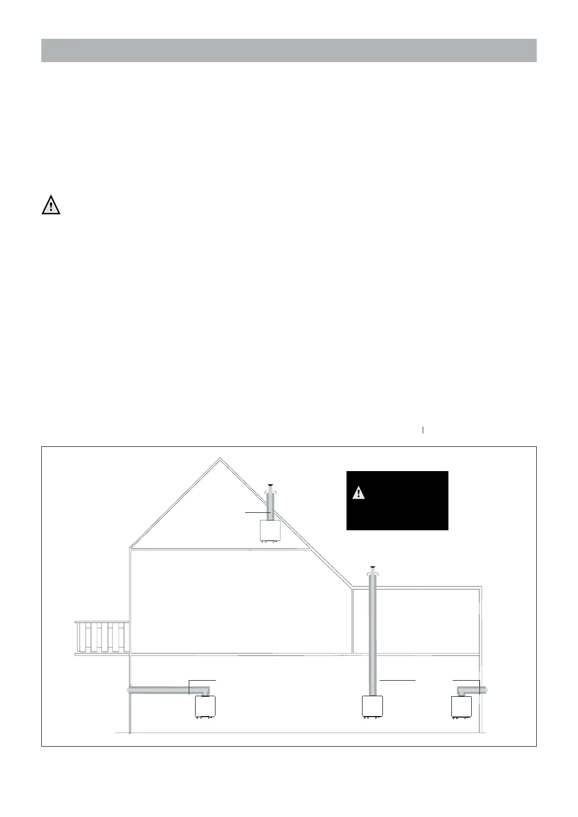
Room sealed system Figure 9.6.a
P/A
P/A P/A
LEGEND:
P/A Polypropylen / Aluminium
Room sealed system
Boiler Class C
Permitted only
when the air
intake and the ue gas
outlet are in the same
pressure area.

 Loading...


