Installation & Servicing instructions ATAG iR-Range
23
9.6.1 Flue terminal locations
The terminal should be located where dispersal of combustion products is not unimpeded and with due
regardforthedamageordiscolourationthatmightoccurtopartsofthebuildinginthevicinity(seeg
9.6.1.c).
In certain weather conditions condensation may also accumulate on the outside of the air inlet pipe. Such
conditions must be considered and where necessary insulation of the inlet pipe may be required.
Incoldand/orhumidweatherwatervapourmaycondenseonleavingtheueterminal.Theeffectofsuch
‘plumeing’ must be considered.
The terminal must not be located in a place where it is likely to cause a nuisance.
For protection of combustibles, refer to IS 813 section 9.10.1. where the terminal is less than 2m (6.6ft)
aboveapavementorplatformtowhichpeoplehaveaccess(including)anybalconyoratroof.Theterminal
must be protected by a guard of durable material.
Where a terminal is tted below a window which is hinged at the top, and where the hinge axis is
horizontal, and the window opens outwards, the terminal shall be 1m below the bottom of the window
opening.
If the boiler is to be located under stairs, a smoke alarm meeting the requirements of I.S. 409 or
equivalent must be tted.
The ue must be terminated in a place not likely to cause a nuisance.
Forhorizontalueterminaldirecttotherearorsidethroughthewall(only1bend
and1wallterminal)theterminalshouldbeplacedhorizontal.Theuepipeinside
theterminalisttedina3degreesangletoensurethecondensationwatercanrun
backtotheboiler.Seegure9.6.1.a.
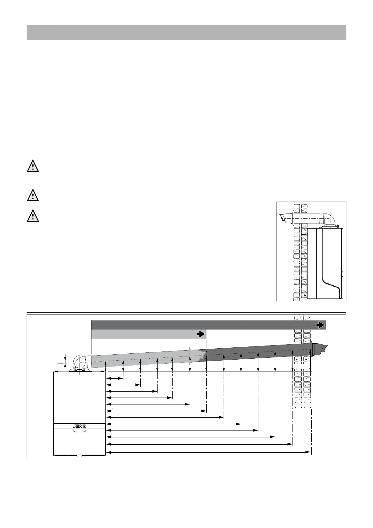
Forlongerhorizontalsections,theoutletsystemshouldalwaysbettedonan
incline(52mm/m=3°)slopingdowntowardstheboilersothatnocondensation
water is able to accumulate in the outlet system. The chances of icicles forming on
the outlet is minimised by causing the condensation water to run back towards the
boiler.Seegure9.6.1.b.
1m
2m
3m
4m
5m
6m
7m
8m
9m
246mm 299mm 351mm 403mm 456mm 508mm 560mm
10m
612mm
11m
716mm
12m
664mm
3°
13m: iC 24/28 iR 12/15/18/24 iS 12/15/18/24
6m: iC 36/40 iR 32/40 iS 32/40
141mm
194mm
89mm
Elbow or
vertical adapter
Figure 9.6.1.a
Figure 9.6.1.b

 Loading...


