Installation & Servicing instructions ATAG iR-Range
26
Example:
An iR24 with a
concentric ue gas system
ø60/100mm has according
to the table a maximum ue
straight length of 13m In the
system that is going to be put
in there are 2 x 45° bends, so
the maximum ue gas length
is 13 – ( 2 x -1.0 ) = 11 m.
ø60/100mm
L
in m
iR 12 Maximum straight length 60/100 13
iR 15 87° bend resistance length 1.6
iR 18 45° bend resistance length 1.0
iR 24
iR 32 Maximum straight length 60/100 6
iR 40 87° bend resistance length 1.6
45° bend resistance length 1.0
Concentric flue system ø60/100mm
Dimensionsuegassystemandairsupplysystem Table9.6.2.a
L
9.6.2 Dimensioning of the ue gas and air intake duct
Thetotallengthoftherunoftheueisdeterminedbytheuediameter,includingfortheconnectionpipe,
elbowsttingsandterminalcoversetc..
Anincorrectdimensioneduesystemcanleadtodisorders.Lookattable9.6.2.aforthechoiceoftheboiler
andthecorrespondingmaximumuelenght.
Explanation table 9.6.2.a:
Concentricuegassystem:
maximumnotedlengthL=distancebetweenboiler(fromelboworverticaladapter)andtheendofterminal
When using bends the noted value behind every bend should be deducted from the maximum straight
length.
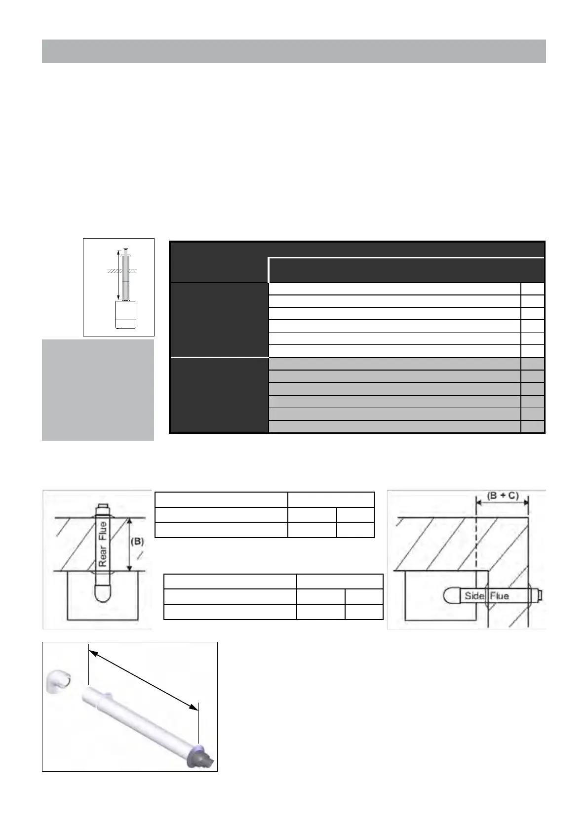
Flue dimensions
Rear Flue B (mm)
Min Max
Telescopicue(FA100100) 280 430
Side Flue B + C (mm)
Min Max
Telescopicue(FA100100) 285 435
Rear Flue
L=wallthickness(B)+150mm
Side Flue
L=wallthickness(B)+distancebetweenboilerandwall(C)+150mm
IfthelengthLismorethan580mmrearueor585mmsideue,thena
Horizontaluexedlength1000mm(60/100mm)withlockfunctionelbow
(FA100250) will need to be used instead, up to 810mm.
L
Figure 9.6.2.a

 Loading...


