Installation & Servicing instructions ATAG iR-Range
25
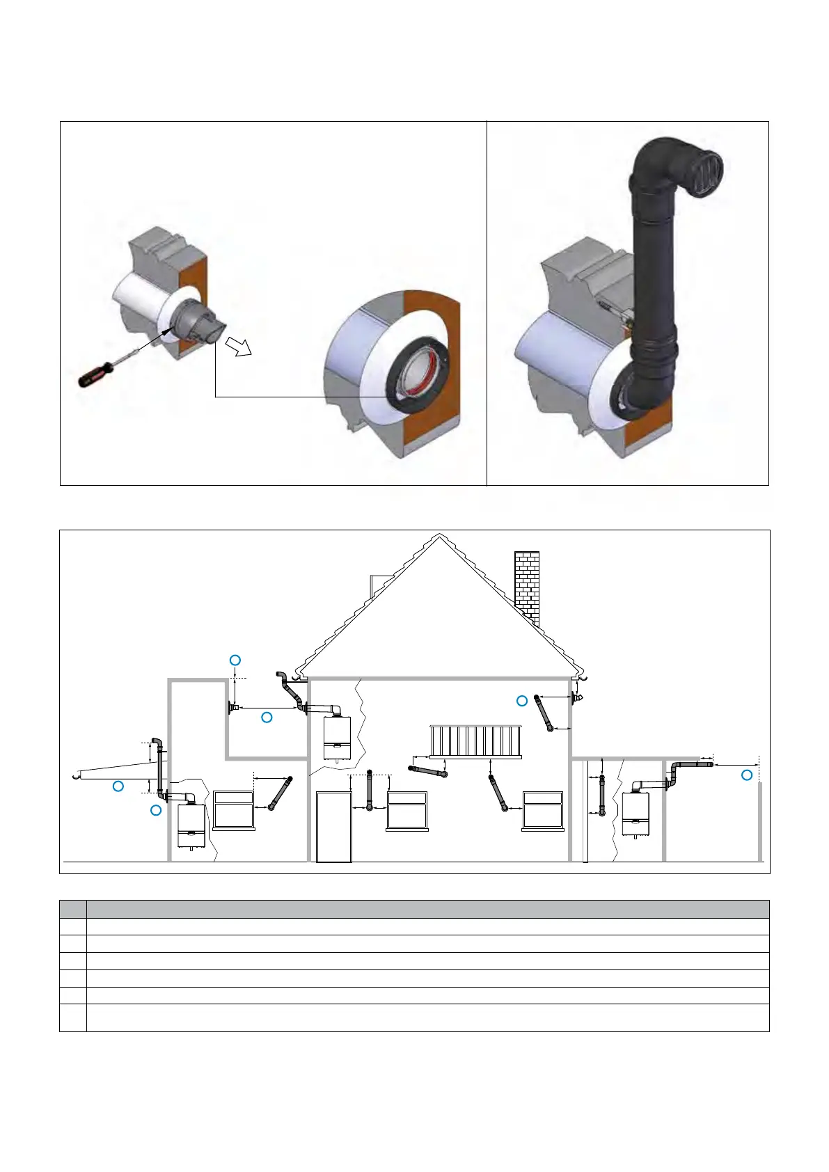
Plume management kit Figure 9.6.1.d
The appliance produces a white wisp of condensate (plumeing). This wisp of condensation is harmless, but
can be unattractive, particularly in the case of outlets in outside walls.
Forwallterminalsaplumemanagementkitisavailableasanoption(seeg.9.8.1.d).
600
100
200
200
25
25
150
200
150
300
150150
200
balcony
300300
150150
window windowwindow door
300
150
200
300
1200
1000
drainpipe
boundary
3
1
2
4
5
6
Terminal position Plume Management Kit (mm)
1 Clearance no less than 200 mm from the lowest point of the balcony or overhang.
2 1,200 mm from an opening in a car port on the same wall i.e. door or window leading into dwelling.
3 Theuecannotbelowerthan1,000mmfromthetopofthelightwellduetothebuildupofcombustionproducts.
4 1,200 mm between air intake and facing terminal.
5 Internal/externalcorners.Theairintakeclearancecanbereducedto150mmprovidingtheueexhaustoutlethasa300mmclearance.
6 600 mm distance to a boundary or surface facing a boundary, unless it will cause a nuisance.
BS 5440: Part 1 recommends that care is taken when siting terminals in relation to boundaries.
Notes:
1. See also Notes on previous page.
2. Plumekitsrunninghorizontallymusthavea10°fallbacktotheboilerforproperdisposalofcondensate.
3. FordetailsonspeciclengthsseerelevantchapterDimensioningoftheuegasandairintakeduct.
4. A terminal must not be sited under a car port roof.
Figure 9.6.1.e

 Loading...


