Installation & Servicing instructions ATAG iR-Range
27
Flue
Air Air
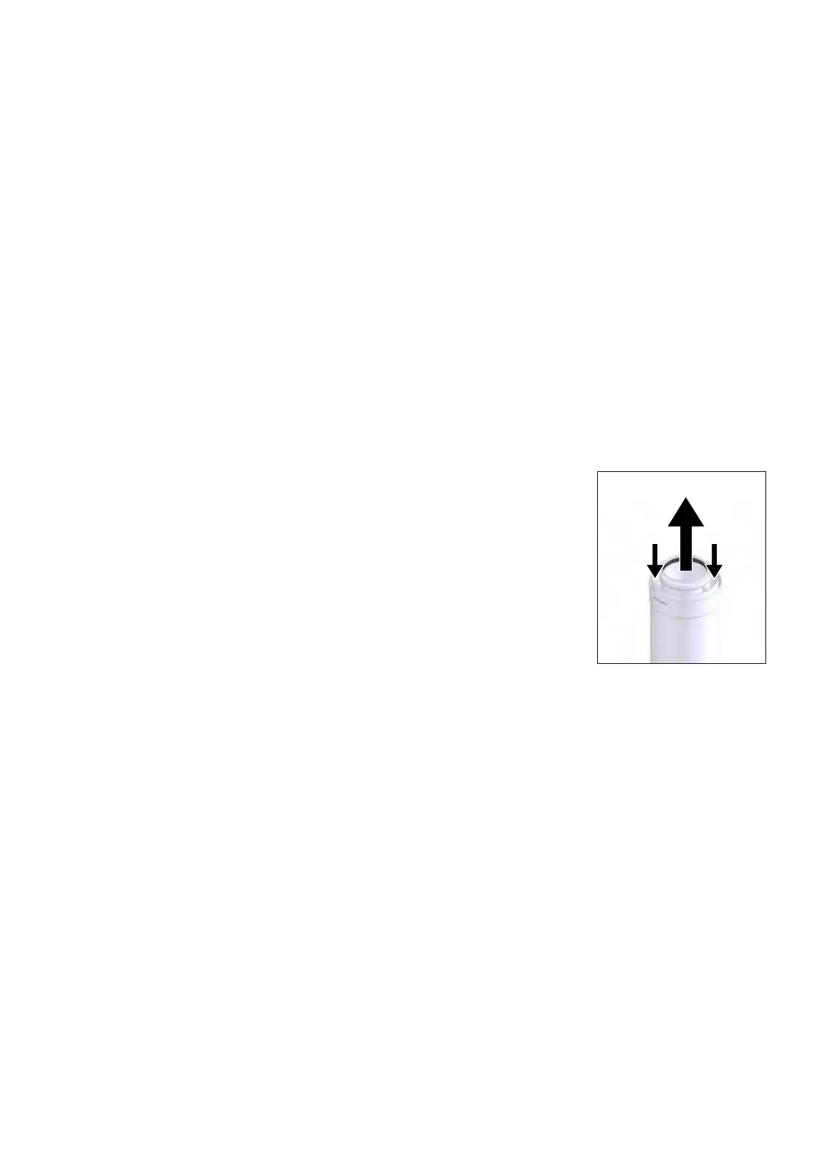
Flow direction Figure 9.6.2.b
Fitting the ue
Note: If it is required to cut an extension, DO NOT cut the end of the inner duct that incorporates the seal
joint.
Ensuretheinnerductendwithoutthesealjointiscutsothatitisushwiththeouterduct.
Ensure that all cuts are square and free from burrs.
Onceassembledwiththecomponentspushedhome,theueisfullysealed.
1. Adjustthetelescopicueandsecurewithsealingtapesuppliedorcutthexedlengthterminaluetothe
required length.
2. Fittheuetotheextensions(ifrequired)bylocatingtheinnerductintothesealjointandpushfullyhome
the inner and outer duct.
3. Whenconnectingthehorizontalueterminallengthensuretheterminalendoutletisattheuppermost
partoftheue.
4. Passtheterminalueassemblythroughthewall.
5. Fit the bend to the boiler and rotate to the correct position and secure in position.
6. Iftheinsidesealingcollar(white)isbeingusedtomakegoodtheinsidewall,thenitwillneedtobetted
beforeassemblingtheue.
7. Pulltheueassemblytowardsthebend,locatingtheinnerductintothesealjointonthebendandsecure
theueassemblytothebendbypushingfullyhome.
8. Makegoodtheoutsidewallbyttingtheoutsidesealingcollar(grey)ontothelocationprovided
immediatelybehindtheueterminalgrille.Makegoodtheinsidewallusingtheinsidesealingcollar
(white) if required.
Whenmountingtheuegassystem,payattentiontotheowdirection(See
gure9.6.2.b).Itisnotpermittedtomountasystemupsidedownandwillleadto
complaints.
Use a soap solvent or special grease (supplied in the accessory bag with the
boiler)tosimplifythetting.

 Loading...


