GB-10
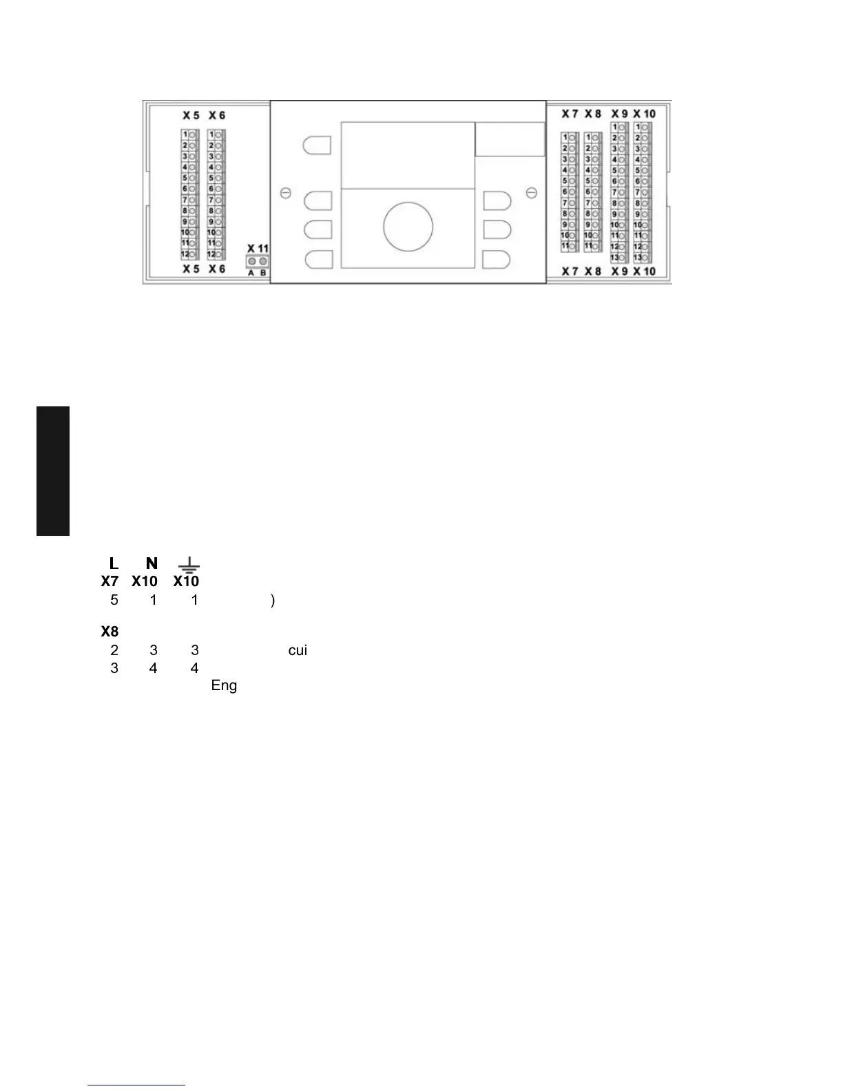
Electrical connections
X5 X6 Sensor- and data bus lines (X5-X6)
1 1 B – Data bus - A (T2B)
2 2 Outdoor sensor ARV20 Mad
3 3 Do not use
4 4 Tank sensor
5 5 Flow sensor mixed circuit 1
6 6 Variable input 1
7 7 Variable input 2
8 8 Variable input 3
9 9 Flow sensor mixed circuit 2
10 10 Do not use
11 11 Do not use
12 12 Do not use
/
//
/1
11
1
X7 X10 X10 Mains connections (X7)
L1 (230V)
X8 X9 X10 Pumps and mixing valve engines (X8, X9, X10)
Unmixed circuit pump
Charge pump
4 5 5 Engine mixing valve 1 (OPEN)
5 Engine mixing valve (CLOS)
6 7 7 Mixed circuit pump 1
7 8 8 Variable output 1
8 9 9 Variable output 2
9 10 10 Engine mixing valve 2 (OPEN)
10 Engine mixing valve 2 (CLOS)
11 12 12 Mixed circuit pump 2
X11 Data bus boiler control unit (X11)
A
Data bus boiler control unit A
B Data bus boiler control unit B
Here, only connect the first MadQ of the data bus connection!
Only connect the A-B data bus boiler control unit (RS485) of the boiler control unit after the first MadQ
control unit from position 20-21 in the boiler to position A-B on X11 in the wall-mounting case. Every
following MadQ control unit (up to 5) must be connected to the A-B data bus (T2B) from position 1 to
X6 and X5.
GB
 Loading...