GB-7
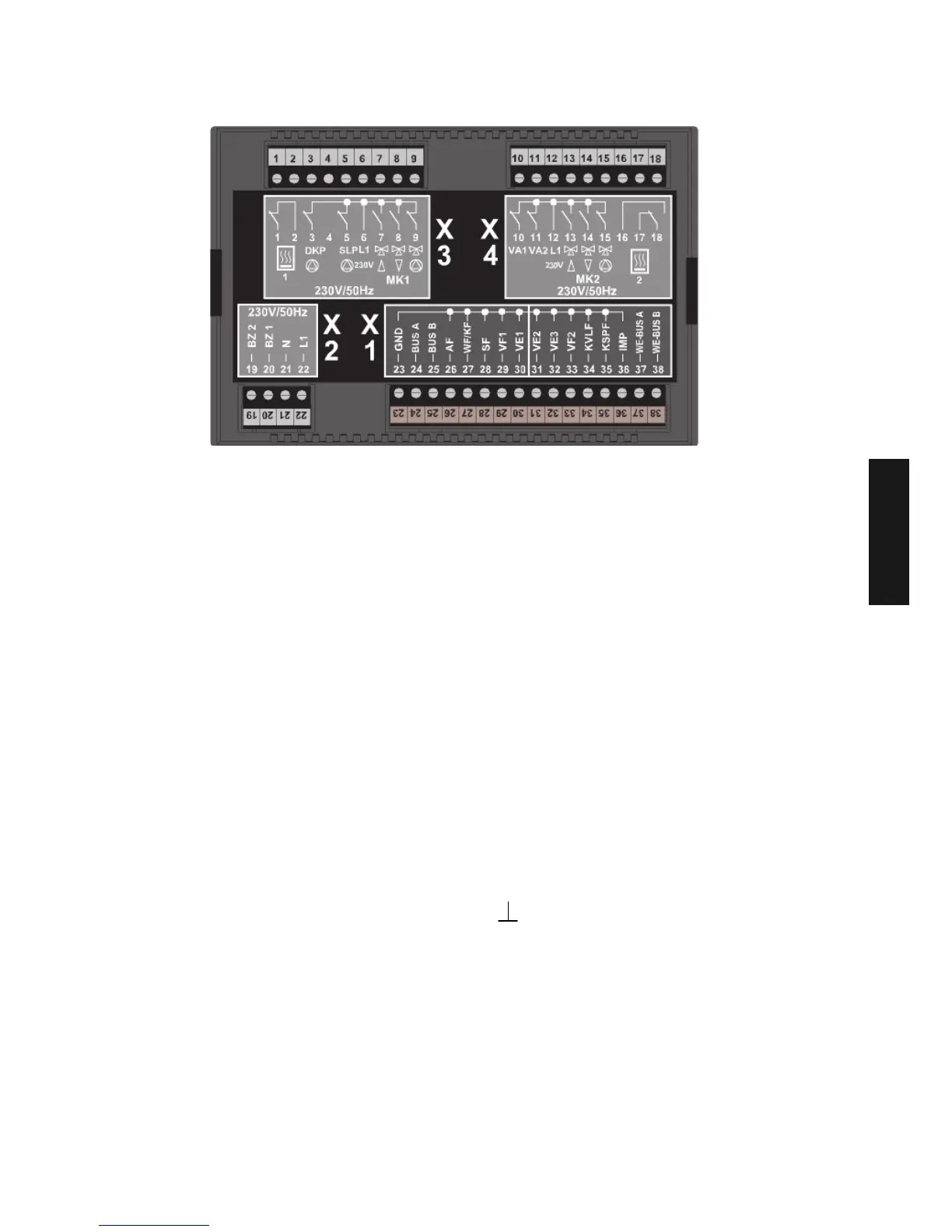
Electrical connection
Mains connection
1 - Do not use
2 - Do not use
3 - Unmixed circuit pump
4 - Do not use
5 - Charge pump
6 - L 1 / 230 V
7 - Mixing valve 1 OPEN
8 - Mixing valve 1 CLOS
9 - Mixed circuit pump 1
10 - Variable output 1
11 - Variable output 2
12 - L 1 / 230 V
13 - Mixing valve 2 OPEN
14 - Mixing valve 2 CLOS
15 - Mixed circuit pump 2
16 - Do not use
17 - Do not use
18 - Do not use
19 - Do not use
20 - Do not use
21 - N / 230 V
22 - L 1 / 230 V
Sensor-/data bus connection
23 - GND for sensor
24 - Data bus connection A
25 - Data bus connection B
26 - Outside sensor ARV20 Mad
27 - Do not use
28 - Tank sensor
29 - Flow sensor mixed circuit 1
30 - Variable input 1
31 - Variable input 2
32 - Variable input 3
33 - Flow sensor mixed circuit 2
34 - Do not use
35 - Do not use
36 - Impulse input
37 - Boiler control unit-data bus A
38 - Boiler control unit-data bus B
GND for sensor
} Mains connection
GB
When building in a MadQ controller into a boiler a data bus connection is made between the
boiler and the controller through the cable loom. In case of a Cascade installation the
positions 20 and 21 of the connection block of each boiler have to be connected to each
other. Adjust Parameter 89 of each boiler to their individual bus address: Boiler 1 = 00, boiler
2 = 01, etc. See also example 17 on page XXXIV.
 Loading...