GB-6
Installation of the control unit
Mounting instructions
Parts necessary for the installation into the
boiler control unit:
- MadQ control unit 23BC or 233BVVC
- MadQ installation set for 23BC or
233BVVC
Parts necessary for the installation into the
wall-mounting case:
- MadQ control unit 23BC or 233BVVC
- MadQ wall-mounting case
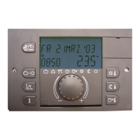
All control units can be built into the
corresponding ATAG boiler control unit or
wall-mounting case after the electrical
connections have been made.
They should be fastened with quick-
clamping devices (1) by turning them
clockwise.
The removal is done in reverse order. See
the assembly instructions that belong to
the MadQ installation set and the MadQ
wall-mounting case.
Electrical installation
The electrical connection and the further
routing to the control units is done on the
back of the unit with the four
terminal strips X1, X2, X3 and X4 in the
boiler control unit, corresponding to the
designations in the coloured terminal
fields.
The routing in the wall-mounting case is
prepared in the factory.
All terminal clamps inside the blue
fields (X1) carry low voltage and may
not get into contact with the mains
voltage! Ignoring this will inevitably
lead to the destruction of the control
unit and to the loss of the basis for
warranty claims!
The terminal clamps in the red fields
(X2...X4), depending on the operation
mode, generally carry mains voltage.
Terminal occupation, see next page.
Note:
When routing the unit, ensure that sensor-
, data bus- and mains lines are routed
separately. Mutual routing inside one
cable is prohibited. Sensor- and data bus
lines may not be routed with mains lines
that supply electrical units that are not
interference suppressed according to EN
60555-2.
230 V~
GB
 Loading...