GB-5
5. The main connection for the heating
system (i.e. boiler control panel -
control unit) must be designed as an
independent electrical circuit. There
should no fluorescent lamps or other
machines, which may be sources of
disturbance, be connected and even
the possibility of such connections
should be ruled out.
6. The outside sensor may not be
installed close to transmitting or
receiving equipment (on garage walls
close to receivers for radio-controlled
garage door openers, amateur radio
antennas, radio controlled alert
systems or close to large scale radio
transmission equipment).
Recommended cable cross-sections
and maximum permitted cable lengths:
For all cables with mains voltage (power
supply, burner, pumps, actuators)
1.5 mm
2
Maximum length:
Unlimited cable length within house
installation.
All low voltage cables (sensors, external
switches due to demands via contact
points, modem connection cables,
analogue signal cables etc.): 0.5 mm
2
Maximum length:
100 m (duplicate wire)
Longer connecting cables should be
avoided in order to reduce the risk of
interfering radiation.
Data bus line: 0.6 mm Ø
Maximum length:
50 m (duplicate wire)
Longer connecting cables should be
avoided in order to reduce the risk of
interfering radiation.
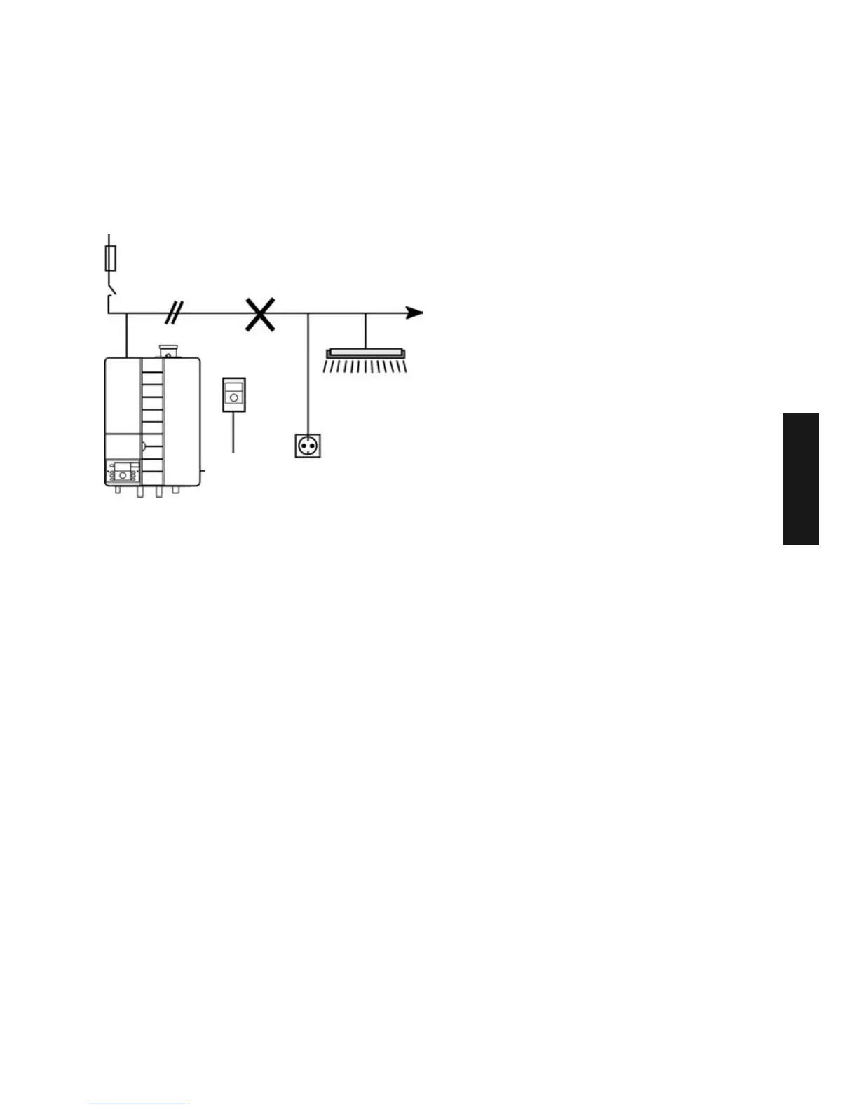
Fuse 16 A
Heating room emergency switch
Only connect heating
room lighting and
sockets on separate
power circuit!
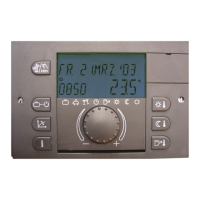
Thermostat
 Loading...