GB-12
Electrical connection
The 2-strand data bus cable is connected
to terminals A and B of the 2-pole terminal
strip on the bottom plate. The connections
are not interchangeable and must be
connected in compliance with the
identification A/B on the base. If the two
connecting lines are mixed up by mistake
the display will be out of function.
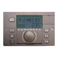
Once the electrical connection is
completed the thermostat is hooked in
flush at the top and folded down, as
shown in the picture, until it audibly
engages into the wall-mounting base.
Electrical connection at control unit
See assembly instructions of the controll
unit.
Data bus allocation
The connection of one or more
thermostats to the control unit occurs via a
two-core data bus line. Because this
connection is always carried out parallel in
the same line, a separate bus address
must be allocated to every thermostat.
Likewise, a separate bus address must be
allocated to every control unit (if there is
more than one, e.g. when the heating
circuit is extended).
Bus address (control unit)
If there is only one control unit, it should
have bus address 10. If there is more than
one control unit in the network (max.: five),
the leading control unit that controls the
boiler control unit, has bus address 10, the
others are allocated in sequence with bus
addresses 20, 30, 40 and 50.
Setting the bus address in the control
unit
The setting of the bus address is carried
out after entering the installer code in the
data bus level of the corresponding control
unit (see commissioning of the control
unit).
Bus address (thermostat)
The allocation of the bus addresses of the
control units and the bus addresses of the
thermostats must be carried out according
to the enclosed table.
Setting the bus address in the thermostat
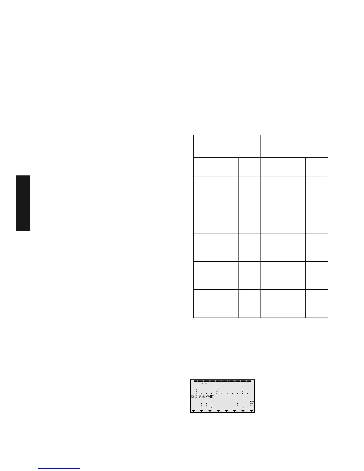
A- Commissioning
After completing the electrical installation
and commissioning the plant, all available
segments appear in the display.
Control unit Thermostat
Function
Bus
address
Heating circuit
Bus
address
Control unit 1 10
Unmixed circ.
Mixed circ. 1
Mixed circ. 2
11
12
13
Control unit 2 20
Unmixed circ.
Mixed circ. 1
Mixed circ. 2
21
22
23
Control unit 3 30
Unmixed circ.
Mixed circ. 1
Mixed circ. 2
31
32
33
Control unit 4 40
Unmixed circ.
Mixed circ. 1
Mixed circ. 2
41
42
43
Control unit 5 50
Unmixed circ.
Mixed circ. 1
Mixed circ. 2
51
52
53
¾
¿
À
Á
Ä
°C
KWh
Min
%
°C
KWh
Min
%
0 2 4 6 8 10 12 14 16 18 20 22 24
 Loading...