SMART ON-OFF LEVEL CONTROLLER
4.3 Wiring
Wiring between LP 400 Level probe to Smart On-Off Level Controller LC 440, 5x1 mm
2
screened (shielded) cable
can be used. For other electrical wirings 1 mm2 normal cable can be used.
Avoid changing terminal blocks places.
The locations of terminals should not be changed. If it is considered that the controller has phase connetiction
to terminal 9 to terminal 19, then the terminal 1 through 8 of the controller should never be connected to the
terminal 9 through terminal 19. Otherwise, this could cause damage to equipment and even it causes personal
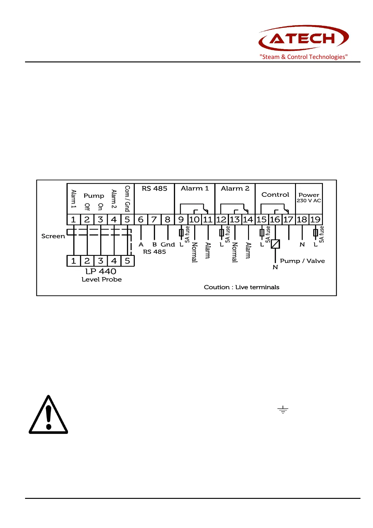
Figure 3 Smart LC 440 On-Off Level Controller wiring diagram
Note: Relays shown in de-energised state.
Note: For wiring of LP 400 On-Off Level Probe, please refer to “LP 400 Level Probe Installation and Operating
At the all phase inputs of the controller, must be used 3A fuse (non-delay type).
Probe cable screen (shield) must be only connected to earth terminal of
probe (Figure 3).
Controller side of the screen must be left unconnected.
Avoid connecting any other earth to 3rd terminal input and must not connected with the other earth on the
"Steam & Control Technologies"