Caution, risk of danger
The PBD only has DC input and output, the positive and negative of it shall not be
connected in reverse. A multimeter shall be used to determine the polarity first, and then
connect into the corresponding input ends of the PBD. Fans of all internal modules in
PBD250 get power supply from PV1. If there are less than 5 strings of PV modules
connected, it has to be connected to PV1.
Cable requirements
5.
4
.
2
DC side wiring
Communication
wire
Model
Battery
Output
Earth wire
Cable Diameter per string:35mm²
Shielded wire: 0.75mm²Shielded wire: 0.75mm²
Cable Diameter:2*120mm²
Cable Diameter per string:35mm²
Cable Diameter per string:300mm²
Cable Diameter:2*120mm²
16mm² 16mm²
Cable Diameter per string:300mm²
PV
PBD250 PBD350
Specific procedures are as follows:
1) Cut off the distribution circuit breaker at the DC side, and ensure that no voltage on the wire at DC side.
2) Use a multimeter to measure the open circuit voltage of the battery to ensure that it is within the
allowed range.
3) Determine the positive and negative pole of the battery with a multimeter.
4) Strip off the insulation skin at the end of the cable
5) Crimpthewiring copper nose.
1. Put the stripped copper core into the crimping hole of the copper nose.
2. Use the terminal pressing machine to press the copper nose tightly. The number of crimping shall be
more than two.
6) install the heat-shrinkable sleeve.
1. Select heat-shrinkable sleeve which is consistent with the cable size, length is about 5cm.
2. The heat-shrinkable sleeve shall be sleeved on the copper nose of the wiring to completely cover the
wire pressing hole of the copper nose.
3. Use a heat blower to tighten the heat-shrinkable sleeve.
7)Connect “Battery-input +"of PBD to the positive pole of battery.
1. Select the bolts that match the copper nose.
2. Connect the copper nose at both ends of the wiring firmly to the "battery input +(BAT+)" end of
PBD and the positive pole of the battery.
3. Tighten the bolts with a screwdriver or wrench.
8)Connect the "battery input -(BAT-)" end of PBD to the negative pole of the battery by cable according
to the method of step 7.
9)cable the "PV input +" end of PBD to the positive pole of the PV module according to step 7.
10)cable the "PV input -" end of PBD to the negative pole of the PV module according to step 7.
11)Please be sure that all wirings are fastened.
5.
4.
3
Earthing
For safety, all PBDs need to be grounded through PE conductors. Make sure the PE copper bar in the PBD
cabinet has been reliably connected with the shell of PBD, and when doing PE connection, the PE grounding
copper bar needs to be reliably connected with the equipotential connection device in the installation site or
electrical control room.And make sure the earthing cable is more than half of the load cable, and earthing
resistance is not lower than 4Ω.
All the wiring inlet and outlet is placed at the bottom of PBD. When all the wiring is completed, the
connection port must be sealed with dust cotton, to prevent dust or animal from entering the PBD.
Connect several connecting wires on the PE copper bar as some parts inside the energy
storage controller need to be grounded, please do not change them without permission, so
as to avoid electric shock
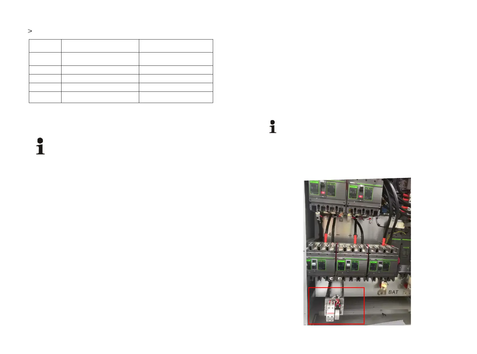
5.4.4 Fan power wiring
The top fan of PBD250 needs AC-220v for power supply, and AC-220 needs to be connected to the
position of the relay below. After the connection is completed, the relay switch needs to be turned on.
19 20