5.5 Communication
The ATESS PBD controller adopts a variety of communication modes.
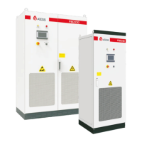
1. Host computerRS485 communication
PBD communicates with each other through RS485 line, and finally connects to our Shinemaster, which
uploads the PBD data to the server through network. It can remotely and real-time monitor the operation
status of single / multiple PBD(s).Terminal blocks are used at both ends of RS485 communication line, by
paralleling the two blocks it will make RS485 line, which shall not exceed 1000m. In order to ensure
transmission quality, special twisted pair shielded communication line shall be applied. The 485 interface is
located in the internal control board CN16 of the machine.
If Shinemaster is not used for monitoring, the user's own monitoring equipment needs to be compatible
with 485 communication protocol of ATESS.
2.CAN communication
CAN communication is required when PBD is equipped with battery with BMS. Connect CAN A of PBD
to the CAN port of battery, and communication can be realized after docking the communication protocol.
The PBD needs to communicate with ATS when applied together, and CAN B of PBD shall be connected
to the can port of bypass cabinet.
Terminal blocks are used at both ends of communication line, by parallelingthetwo blocks itwillmake
a CANline. Special shielded communication line is recommended, which is provided by ATESS.
The CAN A interface is located in the internal control panel CN17, which is a special CAN
communication interface for BMS.
The CAN B interface is located in the internal control panel CN18, which is a special communication
interface for PCS.
3.Parallel communication (special for customized parallel function)
Parallel communication is required when mutiple PBD models are used in parallel.
CAN A communication is adopted for parallel communication, and hand-held connection through CAN
A between PBDs is required to realize mutual communication.
As Parallel function is a special customized function, users cannot parallel the models on their
own.
5
.6.1 Single unit wiring
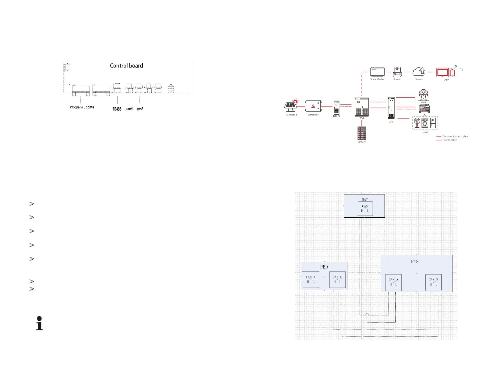
5.6 Wiring single/parallel system and CAN communication
The following is the system wiring diagram of single PBD with PCS:
The following is the system CAN communication wiring diagram of single PBD connected to PCS. PBD250
dose not include battery, and the CAN-A on it control board does not need to be wired. While PBD350
includes a battery pack, thus the CAN-A on PBD control board needs to be wired to the battery CAN port.
The can wiring of the stand-alone system is as follows:
Note: the wiring marked on the manual is for normal use. If the actual wiring is adjusted, the wiring
provided by professionals shall prevail.
21 22