NO
1
2
3
4
5
6
7
8
9
10
11
12
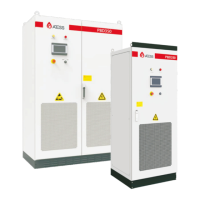
Name
Capacitance
Interface board
Output circuit breaker
Capacitance
Description
Filtering and support
Power supply conversion PCB
Control output and the disconnection of PBD
Filtering and support
IGBT module None
Model
PBD350
The front structural drawing of PBD350 The back structural drawing of PBD350
Sampling board Voltage current temperature sampling PCB
Control board
Main board includes communication interface
Power supply module
Including BUCK board, power source and micro break
PV circuit breaker
Control the disconnection of PV with PBD
Battery circuit breaker Control the connection between battery and PBD
IGBT module None
Fan For cooling the machine
13
14
Inductance
None
Earth terminals
Grounding bronze terminals
3.5 Operation mode define
Optional functions in grid connection mode:
3.5.1 On grid mode
The following operation mode needs to cooperate with PCS energy storage PBD, and the output
terminal of PBD250 / PBD350 should be connected to PCS for use. The mode selection needs to be
made on PCS screen. The PBD350 system is equipped with a battery while pbd250 is not. When it
charges the battery, the battery on PCS side will be charged first by default under all operating
mode, then the PBD battery will be charged secondly; when discharging, the battery with PBD will
be discharged first by default.
Please read section 7.2.4 for operation mode setting method.
In the following description of operating mode, PV means the PV end of PBD.
Activate anti-reflux function(Select on PCS):
1.When the anti-reflex function is activated, feeding power to utility gird is restricted.
2.When anti-reflex function is disabled, can feed power to utility grid.
Please refer to Section 7.2.4 for setup procedure.
3.5.1.1 Load priority mode (anti-reflux function optional)
1. When PV energy is sufficient, PV supply priority to load, the remaining to battery.
2. When PV power is lower than load power, battery discharge automatically. When the battery
voltage gets low to the alarm point, PV and the grid supply power to the load together. To protect
the battery, it will use small power energy to charge the battery, and the battery can supply power
again after recover.
3.5.1.2 Battery priority mode (anti-reflux function optional)
1. When PV energy is sufficient, PV supply priority to battery charge, the remaining to load;
2. When PV power is lower than the charging power, PV supply priority to battery, the grid supplies
to load and battery;
3. If the grid connected backup mode is not discharged or switched to other modes, To maintain
electrochemical activity, the battery will enter the discharge state after one week of current limiting
charging, and the discharge power will be calculated according to battery specifications.
3.5.1.3 On-grid economic priority mode(anti-reflux function optional)
1. Valley price: working logic is the same to battery priority mode’s.
2. Fair price:
A. Battery can neither discharge nor be charged by grid.
B. PV power supply priority to load, the remaining to battery when PV power is higher than load.
C. When PV power is lower than load power, PV and grid supply load, PV doesn’t charge battery.
3. Peak price:
A. Grid will not charge battery.
B. When PV power is higher than load, PV supplies to load , the remaining to battery.
C. When PV power is lower than load power, there are two conditions:
a. When battery voltage is normal, PV and battery supply to load.
b. When the battery is under voltage, battery will not discharge, PV and grid supply to load only, not
to battery.
9 10