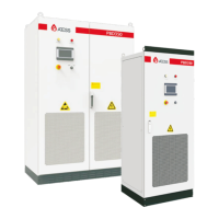
The system wiring diagram of 4 parallel PBDs with 2 PCS is listed below. The output terminals of multiple
PBDs are connected together and then connected to the battery terminal of PCS.
5
.6.
2
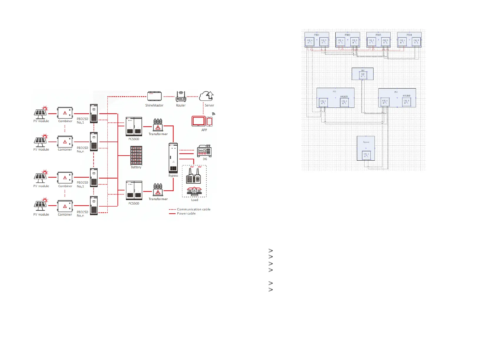
Wiring of paralle system and CAN communication
The following figure is the wiring diagram between the CAN communication of the above system,
including the connection mode and port of CAN communication when multiple PBDs are parallel. If there
are only one or multiple PBDs, the CAN connection port remains the same and the port connected to the
PCs remains the same.
Note: the wiring marked on the manual is for normal use. If the actual wiring needs to be adjusted, the
wiring provided by professionals shall prevail.
6
Commissioning
6.1 Inspection before operation
Before the PBD is put into operation, its installation shall be inspected. At least two staff do the inspection
according to the items listed below to ensure the correctness of the installation.
Inspection items for installation
There is no deformation or damage to PBD.
Bottom of the PBD is fixed securely, the foundation support is stable and reliable.
There is enough space around the PBD.
The temperature, humidity and ventilation conditions of the environment where the PBD is located meet
the requirements.
There is enough cooling air for ventilation.
Cabinet sealing protection is complete and reliable
23
24