3
Product description
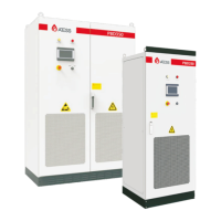
3.1 Energy Storage system
ATESS PBD250/350 is designed for solar charge controlling, The main function is to distribute the
photovoltaic DC power to the energy storage battery. Now it is commonly used with our PCS
energy storage system, as shown in the following system diagram:
3.2 Circuit diagram of the controller
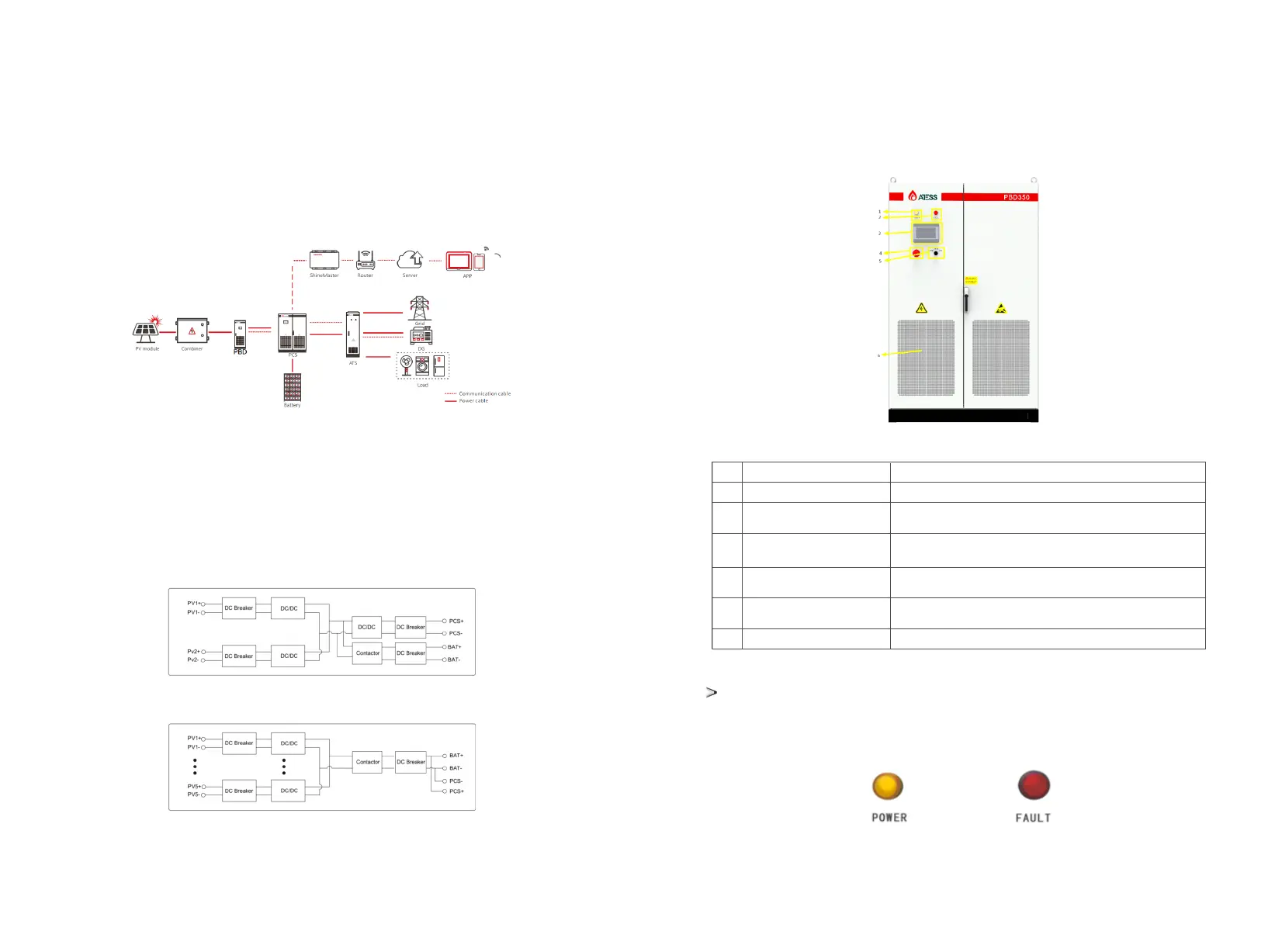
3.3 Layout of the main components
The main external components of PBD include: LED indicator, LCD touch screen, off-on knob,
emergency stop button and other parts.
3.3.1 External components
Appearance description of PBD
The energy storage controller adopts intelligent design. There are two LED indicators on the
controller which is used to display the current status of the PBD.
Indicator
Circuit diagram of PBD350
Circuit diagram of PBD250
NO
Name
Description
1
Power indicator
FAULT
Touch Screen LCD
OFF/ON knob
EMERGENCY STOP
Dust screen
When power supply is normal, the indicator displays yellow.
When PBD is faulty, the indicator displays red.
Operation information display, receive control command and
parameters setting
Control on and off of PBD, turn to on when power on,
and switch to off when power off
Shut down PBD when pressed down
Prevent dust from entering into the controller
2
3
5
4
6
Part description
PBD350 is designed with two-stage BUCK step-up circuit, with batteries in the middle of the two
stages and also in the output, which can be charged through voltage step-down; PBD250 is
designed with one-stage BOOST step-down circuit, with batteries in the output, which can be
charged through voltage step-up.
LED indicators
5 6