Manual, Control Module, PROFINET, DL10
Document #9620-20-C-DL10-04
Pinnacle Park • 1031 Goodworth Drive • Apex, NC 27539 • Tel: 919.772.0115 • Fax: 919.772.8259 • www.ati-ia.com
C-33
2. If the Master is locked, unlock the Master. (This must be done prior to the Master entering the
Tool to prevent the ball bearings from impinging on the Tool bearing race.)
a. If ON, turn the Latch output OFF and turn the Unlatch output ON.
b. The Locked input turns OFF and a short time later the Unlocked input turns ON and
remains ON, indicating that the Tool Changer locking mechanism unlatch operation is
complete. For units with double solenoid valves, after the Unlocked input turns ON the
Unlatch output can be turned OFF.
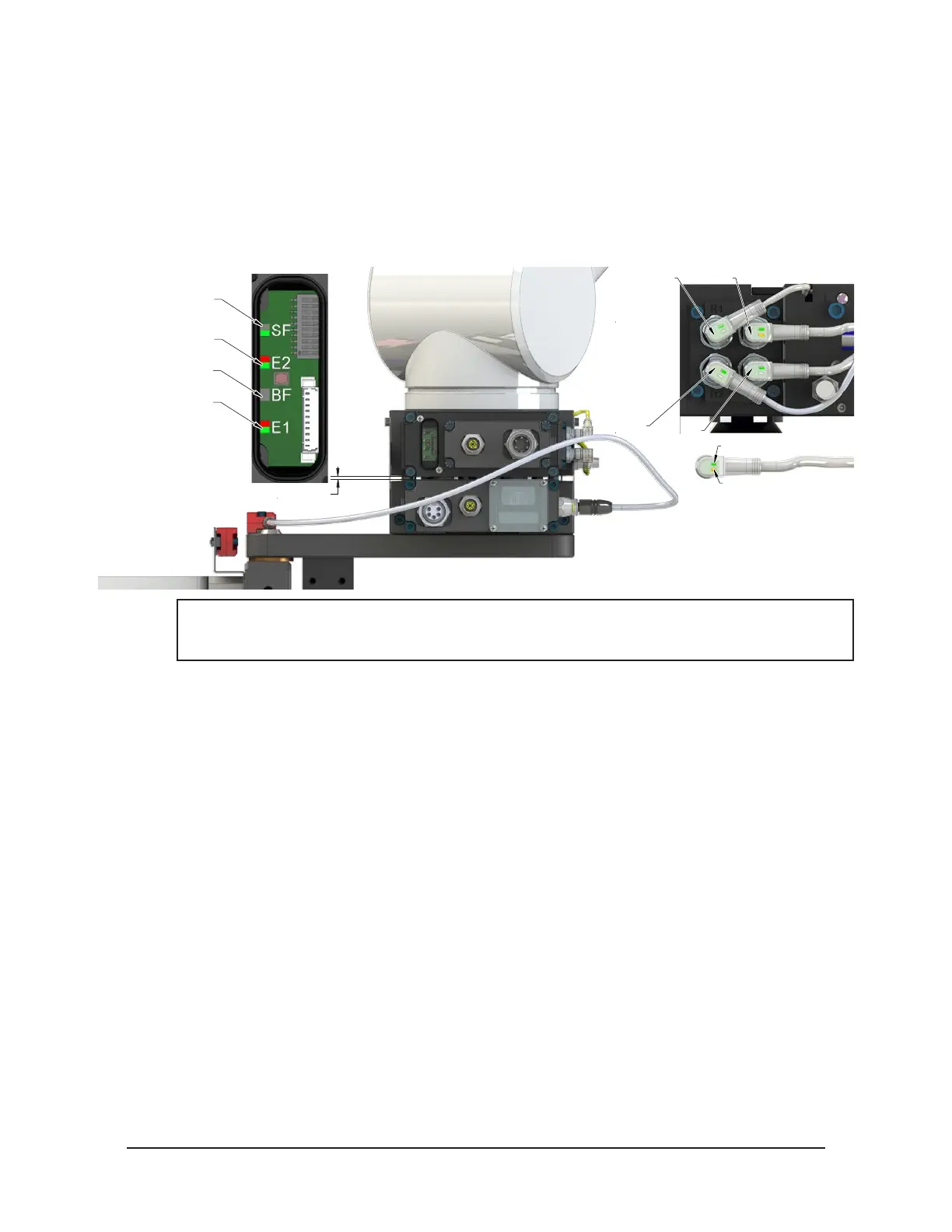
Figure 4.3—Master Moves into Tool and is parallel within 0.06” to 0.15”
RTL (R1)
Unlock (U)
RTL (R2)
Lock (L)
Green LED (Power)
Yellow LED
(Switch Made)
0.06” to 0.15" Away
SF LED is Green
Could see Red Flashing
But should turn Green
E2 LED turns Green
Then Red/Green
BF LED is Off
E1 LED is Red/Green
NOTICE: If the LEDs don’t match what is shown, refer to Section 2.1.2—System Failure (SF)
and Bus Failure (BF) LEDs or Section 2.1.3—Ethernet 1 and Ethernet 2 LEDs for possible
issues.
3. Robot and Master move into the Tool, are parallel and within 0.15” of the Tool, for example: the
module contact pins meet but the RTL sensors have not yet sensed the targets on the tool.
a. The Tool Present and TSIV and TSRV inputs are ON, indicating that the Master and Tool
are in close proximity of each other and verifying the operation of the TSI limit switch.
b. When the Tool Present input is ON, Tool-ID is available within 50 ms.
c. Power is not yet available on the Tool. The bit Tool Power is On is OFF.